10
Installation and maintenance instructions ecoTEC plus 937 0020031552_06
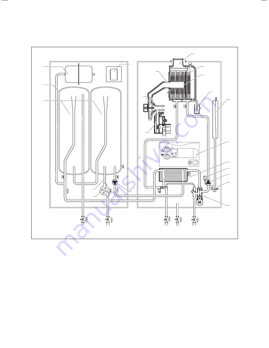
2.5 Functional
description
1
2
3
4
14
13
12
6
7
8
9
11
10
16
17
15
20
19
18
5
c
b
a
21
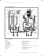
Fig. 2.5 Sequence diagram
Legend:
1 Exhaust
gas
2 Heat
exchanger
3 Combustion
chamber
4 Condensate
siphon
5 Expansion
vessel
6 Operating
display
7 Secondary heat exchanger
8 Automatic air vent
9 Pump
10 Pressure relief valve
11 Diverter
valve
12 Gas valve
13 Fan
14 Compact thermal module
15 Shift load storage tank electronics
16 storage charging pump
17 Aqua-Sensor
18 Stainless steel storage tank
19 Storage tank insulation
20 Expansion vessel
21 opt. accessory 0020057235 for integrating a circulation pump
NTC sensors shift load storage tank
a Storage tank sensor
b Infeed sensor SWT
c Storage tank charging sensor
2 Unit description, data and dimensions
Содержание ecoTEC plus 937
Страница 1: ...For the heating engineer Installation and maintenance instructions GB IE ecoTEC plus 937 VUI...
Страница 74: ...74 Installation and maintenance instructions ecoTEC plus 937 0020031552_06...
Страница 76: ...76 Installation and maintenance instructions ecoTEC plus 937 0020031552_06...
Страница 77: ...Installation and maintenance instructions ecoTEC plus 937 0020031552_06 77...
Страница 78: ......
Страница 79: ......
Страница 80: ...0020031552_06 GBIE 102010 Subject to alterations...


