


34
Installation and maintenance instructions ecoTEC plus 937 0020031552_06
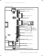
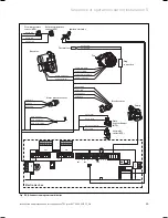
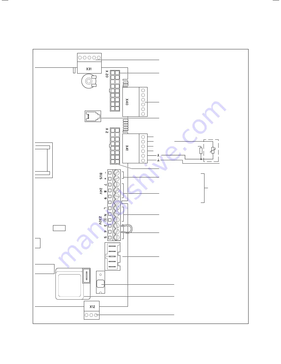
5.19.4
Connection diagrams
Burner cable harness
Wiring harness hydraulics
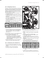
Connection for
external eBUS controller
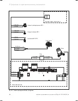
Room thermostat 24 V:
Connection 7, 8 und 9
No bi-directional interface
(only analogue)
Room thermostat 230 V/50 Hz
(Remove bridge when connecting)
Heating pump
2 speed pump (plug with 5 pins)
Mains connection 230 V/50 Hz
Fuse 2 A, slow-acting
Igniter
Attention:
Do not connect
mains voltage
Danger of destroying
the electronics!
Diagnosis via eBUS,
vrnetDIALOG
Accessory module connection
External
sensor
external feed or return
line sensor
Shift load storage tank
pump connection 230 V
Shift load storage tank connection
Shift load storage tank pump connection
Fig. 5.19 Connection diagram electronics box
5 Sequence of operations during installation
Содержание ecoTEC plus 937
Страница 1: ...For the heating engineer Installation and maintenance instructions GB IE ecoTEC plus 937 VUI...
Страница 74: ...74 Installation and maintenance instructions ecoTEC plus 937 0020031552_06...
Страница 76: ...76 Installation and maintenance instructions ecoTEC plus 937 0020031552_06...
Страница 77: ...Installation and maintenance instructions ecoTEC plus 937 0020031552_06 77...
Страница 78: ......
Страница 79: ......
Страница 80: ...0020031552_06 GBIE 102010 Subject to alterations...