background image

Installation and maintenance instructions ecoTEC plus 937 0020031552_06

65

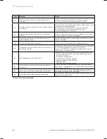
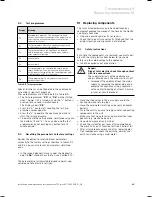
9.2 Test 

programmes

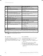
Display

Meaning

P.0

Bleeding test program. The heating circuit and 
the hot water circuit are bled via the automatic air 
vent (the cap of the automatic air vent must be 
released two turns).

P.1

Test programme where the appliance is operated 
in full load after successful ignition.

P.2

Test program where the appliance is operated 
with minimum gas volume (ignition gas volume) 
after successful ignition

P.3

not available

P.4

not available

P.5

Test programme for checking the safety tempe-
rature limitation: The unit is heated by avoidance 
of the regular switch-off by the feed regulator until 
a temperature of 97 °C is reached.

P.6

Filling programme: The diverter valve moves to 
the centre position.

Table 9.5 Test programmes

Special functions can be triggered in the appliance by 
activating various test programs.
These programmes are listed in detail in Table 8.5.

The test programmes “

P.0

” to “

P.6

” will be started 

when " Power ON“ is turned on and the "+“ button is 
pressed for 5 seconds simultaneously.
The display shows "

P.0

“.

Press the "

+

" key to start counting the test pro-

gramme number upwards.
Press the "

i

“ to operate the appliance now and to 

start the test programme.
To de-activate the setting mode, simultaneously push 
the buttons "

i

“ and "

+

“. You can also end the test 

programmes by not pushing any button for a 15 
minute period.

9.3 

Resetting the parameters to factory settings

Besides the option to reset individual parameters 
manually to the factory settings specified in Tables 9.2 
and 9.3, you can also reset all parameters simultane-
ously.

In the second diagnostic level, under the diagnostic 
point "d.

96

" change the value to 1 (see Section 9.1.2).

The parameters of all adjustable diagnosis points now 
correspond to the factory settings.

>

>

>

>

>

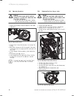
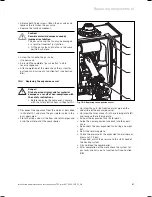
10 Replacing 

components

The tasks listed below may only be undertaken by a 
competent engineer approved at the time by the Health 
and Safety Executive.

Only use genuine spare parts for repairs.
Check that the parts are correctly fitted and that the 
original location and alignment is maintained.

10.1 Safety 

instructions

Each time the components are replaced, you must com-
ply with the safety instructions below for your own 
safety and to avoid damage to the appliance.

Take the appliance out of operation.

e

 Danger!

Risk of fatal electric shock through contact 
with live connections.

The supply terminals of the appliance are 
under voltage even if the mains switch is off.

Disconnect the appliance from the mains 
supply by removing the power plug or de-
energise the appliance using a separator 
with a contact opening of at least 3 mm (e.
g. fuses or circuit breakers).

Close the stop valves in the gas supply and in the 
heating flow and return pipes.
Close the cold water inlet stop valve (only on combi 
boilers).
Drain the unit if you wish to replace water-conducting 
components in the unit.
Make sure that no water drips on live electrical com-
ponents (e.g. electronic box etc.).
Use only new gaskets and O-rings.
Check the system for gas leaks after completion of 
the work. Carry out a function test (see Section 7.8).
After all maintenance work and after replacing elec-
trical components check the earthing, polarity and 
earth resistance using a multi-meter.

>
>

>

>

>

>

>

>

>
>

>

Troubleshooting 9

Replacing components 10

Содержание ecoTEC plus 937

Страница 1: ...For the heating engineer Installation and maintenance instructions GB IE ecoTEC plus 937 VUI...

Страница 2: ...ing the location for the shift load storage tank and combination boiler 23 5 3 Unpacking the equipment 23 5 4 Using the installation template 24 5 5 Flue exit 24 5 6 Installation of the flue gas syste...

Страница 3: ...8 2 Maintaining the compact thermal module 53 8 2 1 Removing the compact thermal module 53 8 2 2 Cleaning the integral condensation heat exchanger 54 8 2 3 Checking the burner 54 8 2 4 Installing the...

Страница 4: ...he environment i Symbol denoting additional useful tips and information Symbol for a required task 1 4 Validity of the manual This installation manual applies exclusively to the unit with the followin...

Страница 5: ...p an expansion vessel a diverter valve and a 15 l layered storage tank The shift load storage tank and combination boiler can be easily mounted on an internal wall and installed with a vertical or hor...

Страница 6: ...pressure central heating 3 0 bar Volume of water circulating 20 K 1204 l h Approximating condensation water volume at 50 C Feed 30 C Return 2 9 l hr Pump head 250 mbar Minimum water flow 0 1 l min Sp...

Страница 7: ...return pipe 22 mm 2 Cold water connection 15 mm 3 Gas connection 22 mm 4 Hot water connection 15 mm 5 Heating flow pipe 22 mm 6 Hanging bracket 7 Flue hole flue system 60 100 8 Flue hole flue system...

Страница 8: ...2 3 4 5 7 8 Fig 2 2 Dimensions shift load storage tank Legend 1 Heating return pipe 22 mm 2 Cold water connection 15 mm 3 Gas connection 22 mm 4 Hot water connection 15 mm 5 Heating flow pipe 22 mm 6...

Страница 9: ...k charging pump 1 2 3 4 6 5 7 8 13 12 10 9 11 Fig 2 3 Function elements combi unit Legend 1 Expansion vessel combi boiler 2 Air intake pipe 3 Compact thermal module 4 Ignition electrode 5 Fan 6 Divert...

Страница 10: ...condary heat exchanger 8 Automatic air vent 9 Pump 10 Pressure relief valve 11 Diverter valve 12 Gas valve 13 Fan 14 Compact thermal module 15 Shift load storage tank electronics 16 storage charging p...

Страница 11: ...g system can be filled using the filling devices fitted to the ecoTEC plus combination boilers The ecoTEC plus 937 is be supplied for natural gas and can be converted for propane gas with a conversion...

Страница 12: ...s If possible open doors and windows fully and ensure air is circulating Avoid the use of naked flames e g lighters matches Do not smoke Do not use any electrical switches plugs doorbells telephones o...

Страница 13: ...ing British Standards BS 6700 Services supplying water for domestic use within buildings and their curtilages BS 6798 Specification for installation of gas fired boil ers not exceeding 60 kW input BS...

Страница 14: ...ecommendations for combi boilers The installation location for the combi boiler and shift load storage tank must permit proper connection of the flue gas system to the combi boiler In addition there m...

Страница 15: ...in substances of this type which can cause corrosion in the flue gas system in the worst case even if the unit is operated as an open vent appliance Particularly in hairdressing salons lacquering and...

Страница 16: ...terminal position must be located in such a position that any flammable gases can be freely dissipated b A plume of water vapour will sometimes be visi ble from the flue terminal Positions where this...

Страница 17: ...inal should be extended as shown in Fig 3 7 2 Dimension F These dimensions can be reduced to 25 mm without having a negative effect on the output of the combi boiler However in order to ensure that th...

Страница 18: ...for use of system cleaning agents can be obtained from Sentinel Betz Dearborn Ltd Widnes Cheshire WA8 8UD Tel 0151 420 9595 or Fernox Alpha Fry Technolo gies Tandem House Marlow Way Croydon CR0 4XS Te...

Страница 19: ...ments 2 of the specific system volume nominal capacity in litres heat ing output in case of multiple boiler systems the lowest indi vidual heating output should be used These data only apply up to 3x...

Страница 20: ...me by the adjacent factors 0 109 0 156 Table 4 5 Size of an additional expansion vessel 4 8 6 Shift load storage tank expansion vessel The shift load storage tank is fitted with a 1 litre expan sion v...

Страница 21: ...s slippery or wet surfaces and climbing steps and stairs Always use assistance if required Carriage of carton from point of delivery to point of installation first or higher floor cellar Recommend 2 p...

Страница 22: ...ut resistant gloves with good grip to protect against sharp edges and ensure good grip when handling appliance Positioning of Appliance for Final Installation within compartment etc restricting instal...

Страница 23: ...st be visible i If the boiler is to be installed in a timber framed building it should be fitted in accord ance with IG UP 7 Edition 2 Gas installations in timber framed and light steel framed build i...

Страница 24: ...inadequate installation The combi heater may come loose from the wall and fall if the wall or fixing material is unsuitable Only install the appliance on a firm sealed wall surface that has a sufficie...

Страница 25: ...ket i If the appliance is to be fitted in a timber framed building ensure that the hanging bracket is secured to a substantial part of the timber frame capable of taking the full weight of the applian...

Страница 26: ...an additional expansion vessel see Sec tion 4 8 6 5 11 Gas connection a Danger Risk of death caused by improper gas installation An improper gas installation may impair the operational safety of the a...

Страница 27: ...combi boiler Tighten all connections Purge the gas pipe before commissioning Check the gas connection for leaks using leak detect ing spray 5 12 Connecting the hot and cold water a Danger Risk of scal...

Страница 28: ...pump we recom mend using the accessory set Item no 0020057235 i Using a circulation pump negatively affects hot water comfort as it causes turbulence and disrupts the stratification in the tank Limit...

Страница 29: ...urn heating connections Remove the stop valves with union nuts olives and fibre seals from the box of accessories for the combi boiler Insert the fibre seal 1 and screw the stop valve 2 onto the retur...

Страница 30: ...e in a suitable location e g a preferably the drain line should run and termi nate internally to the house soil and vent stack at least 450 mm above the invert of the stack A trap giving a water seal...

Страница 31: ...and no cable or other electrical components can be damaged if water or steam is discharged Please note that the end of the discharge pipe must be visible i We recommend that the discharge pipe for the...

Страница 32: ...mains supply at terminals 7 8 9 and BUS Only connect the mains supply cable to the terminals marked for the purpose The appliance is designed for connection to 230 V 50 Hz supply with a 3 A rating Co...

Страница 33: ...connector X31 onto the plug socket X31 2 left hand side of the printed circuit board Fix the cable 4 in the electronics box via the cable clamps 5 19 3 Establishing the power supply b Caution Risk of...

Страница 34: ...when connecting Heating pump 2 speed pump plug with 5 pins Mains connection 230 V 50 Hz Fuse 2 A slow acting Igniter Attention Do not connect mains voltage Danger of destroying the electronics Diagno...

Страница 35: ...ck X 20 7 black X 20 8 blue X 2 12 green X 2 11 red X 2 9 black Pump X 20 18 red 24 VDC X 20 9 blue Erde X 20 16 blue Earth X 20 13 black X 20 12 black X 20 4 grey PWM X 20 3 black Hall Signal X 20 17...

Страница 36: ...lack Pump X 1 7 Green X 1 1 Black X 1 8 red Storage tank sensor NTC X 1 4 orange X 1 1 Black Plug connection Aqua Sensor Shift load storage tank electronics X 1 2 brown X 1 1 Black X 1 2 Brown X 1 1 B...

Страница 37: ...Accessories Item no Connection VR 65 control centre for UK cylinder installation eBUS 307215 System solution for UK cylinder connection vrDIALOG 810 2 0020023370 Diagnostic software Table 5 1 Vaillant...

Страница 38: ...thermostat This frost protection ther mostat should be connected to the terminals 3 and 4 on the combi boiler in parallel to all the other external heating controllers i External frost protection dev...

Страница 39: ...ck all hot and cold water pipes for leaks 6 4 Filling and bleeding the heating system i Use the following test programmes for filling and venting the heating system Filling the heating system Use the...

Страница 40: ...system for the first time i If the water pressure in the heating system is too low the display switches between error message F 22 and the display of the actual pressure when the unit is switched on...

Страница 41: ...er stop valve 6 6 Filling the condensate drain trap a Danger Risk of poisoning from escaping exhaust gas If the appliance is operated with an empty condensate trap exhaust gas may escape and cause poi...

Страница 42: ...instructions enclosed with this boiler and as described below a visual check is carried out on the boiler combus tion circuit and the relevant seals that any defects have been corrected at this stage...

Страница 43: ...operation by Pressing the and i buttons simultaneously and turn down both thermostat control knobs Allow the boiler to cool down by turning off water taps and allow pump overrun to operate for a mini...

Страница 44: ...ove the pressure gauge and re tighten the seal ing screw 1 Open the gas isolation valve of the boiler Make sure that there is no leakage at the sealing screw Put the front casing back on Reset boiler...

Страница 45: ...before commissioning the appliance and handing over to the user Commission the appliance in accordance with the instructions in the relevant operating manual Check the gas supply pipework the flue sy...

Страница 46: ...can set the following temperatures using the knob for hot water draw off temperature Knob setting c 35 C Knob setting a 65 C a a b c c 1 1 1 Fig 7 4 Setting range for the storage tank temperature If t...

Страница 47: ...is to be protected by an inhibitor it should be added at this stage in accordance with the manufacturer s instructions Further information can be obtained from Sentinel Betz Dearborn Ltd Tel 0151 420...

Страница 48: ...rop erty due to neglected inspection and main tenance Neglected inspection and maintenance works or not observing the stated inspection and maintenance intervals can interfere with the operational saf...

Страница 49: ...gas duct 8 1 1 General inspection and maintenance instructions To ensure the faultless operation long term availability of all functions and long working life of your Vaillant boiler and to prevent mo...

Страница 50: ...and water leaks If necessary refill and re bleed the heating installa tion Replace the front casing to the boiler Carry out a functional check of the boiler see section 7 Always check earth continuit...

Страница 51: ...e value stabilises Liquid gas Only perform the adjustment in very small increments approximately 1 16 turns and wait approximately 1 minute after each adjustment until the value stabilises After perfo...

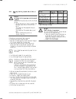
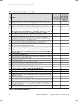
Страница 52: ...as isolation valve and the service valves x 9 Dump the pressure in the boiler on the water side observe pressure gauge and check the charge pressure of the expansion vessel of the boiler Top up if nec...

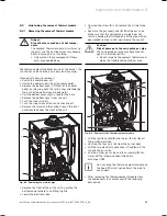
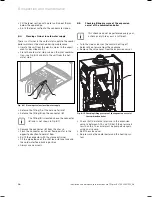
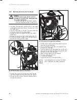
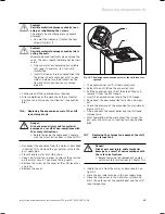
Страница 53: ...1 Fig 8 2 Removing the air inlet pipe Remove the front of the of the unit by pulling the bottom edge forwards and lifting slightly Lower the electronic box Unscrew the screw 2 and remove the air inlet...

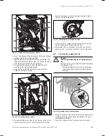
Страница 54: ...condensate siphon Avoid pointing the water jet directly at the insulating sur face 2 on the back of the heat exchanger If necessary the heat exchanger can be cleaned using ordinary vinegar 8 2 3 Chec...

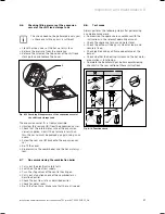
Страница 55: ...ctly located Use the flats of the spanner on the flexible gas pipe to hold the gas fittings in position 11 Fig 8 9 Checking the gas supply for leaks Turn on the gas supply and check for leaks Pay par...

Страница 56: ...11 Remove the connector 2 from the chassis Flush the connector out under flowing water in the opposite direction to normal flow Re fit the connector with the cleaned strainer Fit the pipe elbows of th...

Страница 57: ...ves sel Re fit the cover Re pressurise the combi boiler and the hot water sys tem 8 7 Re commissioning the combination boiler Carry out the electrical safety tests Switch on the electrical supply Tur...

Страница 58: ...eating System Check that the stop valves in the flow and return lines of the combi boiler are open Check that the mains switch is set to ON Set the temperature of the central heating to Maxi mum Set t...

Страница 59: ...eriod of the opera tion block function due to water shortage tempera ture gradient S 96 Return flow sensor test heat demands hot water or heating are blocked S 97 Water pressure sensor test heat deman...

Страница 60: ...hot water circulation pump via accessory mod ule 1 to 100 on 0 off d 22 Hot water demand 1 on 0 off d 23 Summer winter function 1 Winter 0 Summer d 25 Hot water activation via eBUS controller 1 yes 0...

Страница 61: ...ctor hood 5 External gas valve 6 External error message d 28 Switching relay 2 on the accessories module 1 Circulation pump 2 Ext pump factory setting 3 External cylinder charging pump 4 Flue gas flap...

Страница 62: ...W 0 1 5 l min and no delay 1 3 7 l min and 2s delay d 92 Module recognition shift load storage tank Setting range 0 not recognised 1 no communication via PE BUS Module recognised earlier 2 Communicati...

Страница 63: ...e wiring harness open circuit Wiring harness thermo compact module faulty F 27 Incorrect sensing of flame Flame monitor faulty F 28 Unit will not start Attempts to ignite during start failed Faults in...

Страница 64: ...er F 80 Interruption or short circuit of SWT inlet sensor only in conjunction with F 91 NTC defective NTC cable defective defective plug connection at NTC defective plug connection at APC electronics...

Страница 65: ...n Tables 9 2 and 9 3 you can also reset all parameters simultane ously In the second diagnostic level under the diagnostic point d 96 change the value to 1 see Section 9 1 2 The parameters of all adju...

Страница 66: ...k check the system for gas leaks and carry out a function test see Sec tion 8 8 i A new burner door seal kit must be fitted every time the burner door is removed 10 3 Replacing the fan or the gas valv...

Страница 67: ...cing the component comply with the safety instructions in Chapter 10 1 Disconnect the appliance from the mains as described in Chapter 10 1 and close the gas isolator valve in the gas supply pipe Clos...

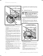
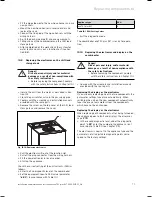
Страница 68: ...ate pipe which runs from the pri mary heat exchanger to the siphon 1 2 4 3 Fig 10 5 Replacing the primary heat exchanger Remove the clamps 1 and 2 and pull off the flow and return hoses from the prima...

Страница 69: ...nd close the gas isolator valve in the gas supply pipe Close the cold water inlet stop valve Open a hot water tap in order to release the pressure on the water circuit Then close the tap again Remove...

Страница 70: ...rging pump in reverse order and use new gaskets Connect the electrical wires of the pump in reverse sequence Check for correct routing of the lines Re fit the discharge pipe 1 and use new gaskets Fill...

Страница 71: ...der Start up the appliance Check the correct setting of the unit variants DSN as follows Enter the 2nd diagnostic level of the combi boiler Set the equipment specific DSN value parameter d 93 in accor...

Страница 72: ...usehold waste Ensure that old appliances and any existing accessories are disposed of properly Packaging The specialist company that installed the appliance is responsible for disposing of the transpo...

Страница 73: ...Installation and maintenance instructions ecoTEC plus 937 0020031552_06 73 EC declaration of conformity EC declaration of conformity...

Страница 74: ...74 Installation and maintenance instructions ecoTEC plus 937 0020031552_06...

Страница 75: ...Installation and maintenance instructions ecoTEC plus 937 0020031552_06 75 Installation Commissioning and Service Record...

Страница 76: ...76 Installation and maintenance instructions ecoTEC plus 937 0020031552_06...

Страница 77: ...Installation and maintenance instructions ecoTEC plus 937 0020031552_06 77...

Страница 78: ......

Страница 79: ......

Страница 80: ...0020031552_06 GBIE 102010 Subject to alterations...

Отзывы: