Installation and maintenance instructions ecoTEC plus 937 0020031552_06
33
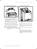
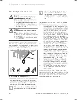
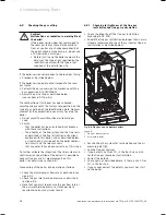
Pull the electronics box forward and lower.
Unclip the back cover of the electronics box and lift
the cover upwards to reveal the connections.
1
2
3
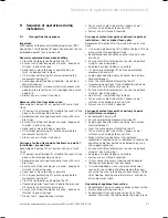
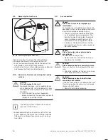
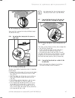
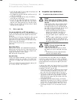
Fig. 4.16 Cable run on the underside of the unit
Feed the wiring harness (
2
) of the shift load storage
tank with the grommets (
3
) through the cable entries
provided on the shift load storage tank and on the
combi boiler.
On the combi boiler use the cable entry at the very
front (
1
).
Fix the grommets to the cable entries using the
spring clamps provided.
- + 7 8 9
L N
3 4 5
X3
1
X12
1
2
3
5
4
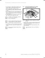
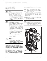
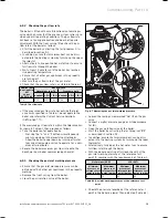
Fig. 4.17 Cable routing in the electronics box
Run the pump cable
X12
(
3
) outside the electronics
box.
Push the plug
X12
of the pump cable onto the plug
socket
X12
(
5
) on the printed circuit board.
Run the sensor cable (
1
) with plug
X31
to the printed
circuit board.
Push the flat connector
X31
onto the plug socket
X31
(
2
) (left-hand side of the printed circuit board).
Fix the cable (
4
) in the electronics box via the cable
clamps.
>
>
>
>
>
>
>
>
>
5.19.3 Establishing the power supply
b
Caution!
Risk of damage to the appliance.
The electronics may be damaged via a mains
supply at terminals 7, 8, 9 and "BUS".
Only connect the mains supply cable to the
terminals marked for the purpose.
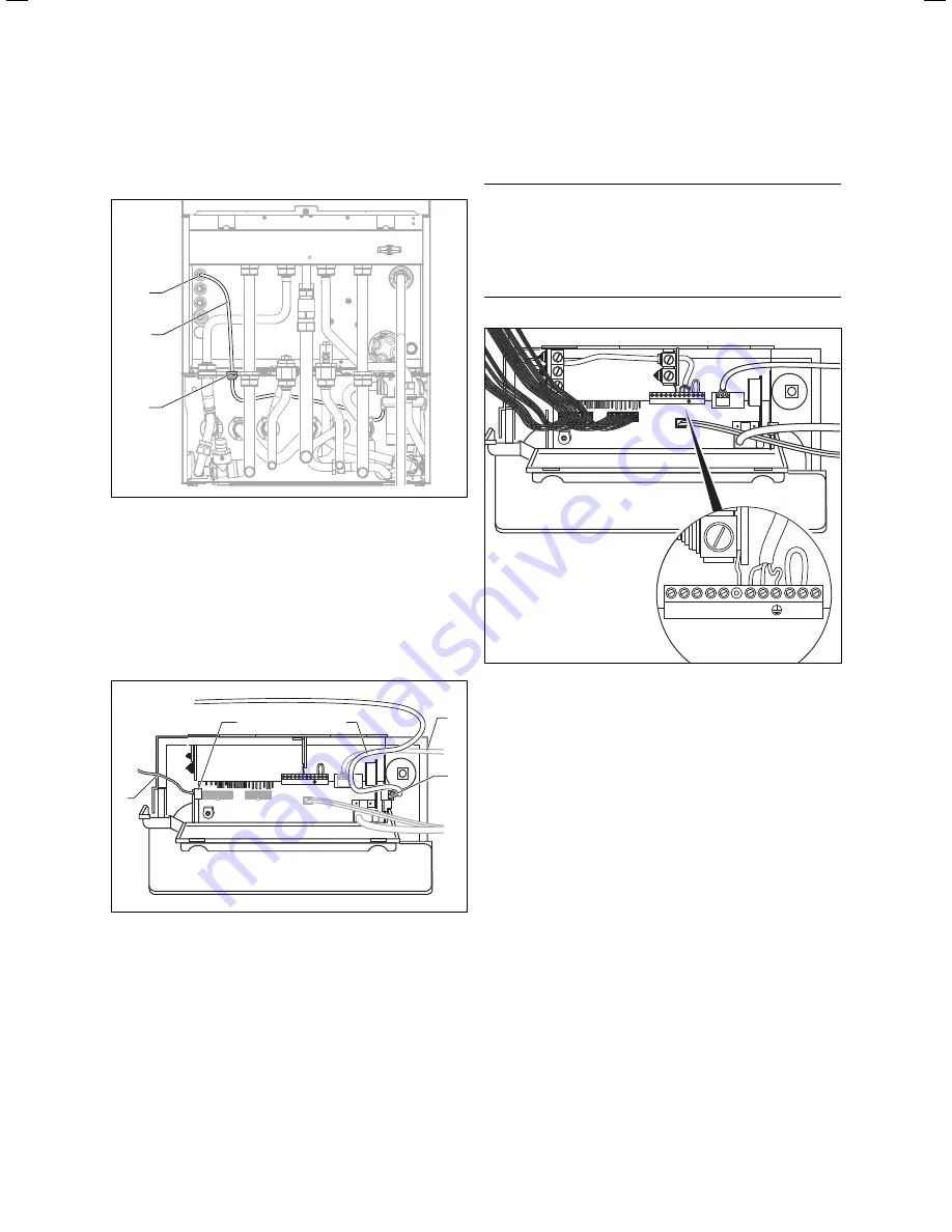
- + 7 8 9
L N
3 4 5
- + 7 8 9
L N
3 4 5
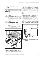
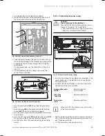
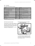
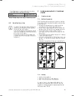
Fig. 5.18 Connecting the power supply
Run the flex through the cable entries provided in the
combi boiler and in the electronics box and tighten
the cable clamps.
Connect the flex to terminals L and N and the earth
connection of the terminal block.
Green-yellow wire
(earth)
Boiler connection
earth symbol
Blue wire
(neutral)
Boiler connection N
Brown wire
(live)
Boiler connection L
i
Make sure that the cables are securely fixed
in the terminal blocks.
Refit the electronics box cover by pushing into place
until it clips back into position ensuring all wires are
not trapped or pinched.
Lift the electronics box up and secure.
>
>
>
>
>
Sequence of operations during installation 5
Содержание ecoTEC plus 937
Страница 1: ...For the heating engineer Installation and maintenance instructions GB IE ecoTEC plus 937 VUI...
Страница 74: ...74 Installation and maintenance instructions ecoTEC plus 937 0020031552_06...
Страница 76: ...76 Installation and maintenance instructions ecoTEC plus 937 0020031552_06...
Страница 77: ...Installation and maintenance instructions ecoTEC plus 937 0020031552_06 77...
Страница 78: ......
Страница 79: ......
Страница 80: ...0020031552_06 GBIE 102010 Subject to alterations...

