10
vacon
X
5
EIP
01
Ethernet IP with
115
VAC / Encoder Interface Option Board
Getting Started
To begin communicating with the drive over Modbus / TCP, the drive’s IP address must be set (use parameters 922-
925). After setting the IP address, cycle power off and on for the new address to take effect.
For information on setting parameters, see the X5 User’s Manual.
I/O Messaging
Input / Output (I/O) polling messages are for time-critical, control-oriented data. The messages are transferred
between the devices all the time and are used for continuous control of the frequency converter. They provide a
dedicated, special-purpose communication path between a producing application (master) and one or more
consuming applications (slaves). They are exchanged across single- or multi-cast connections and typically use
high-priority identifiers.
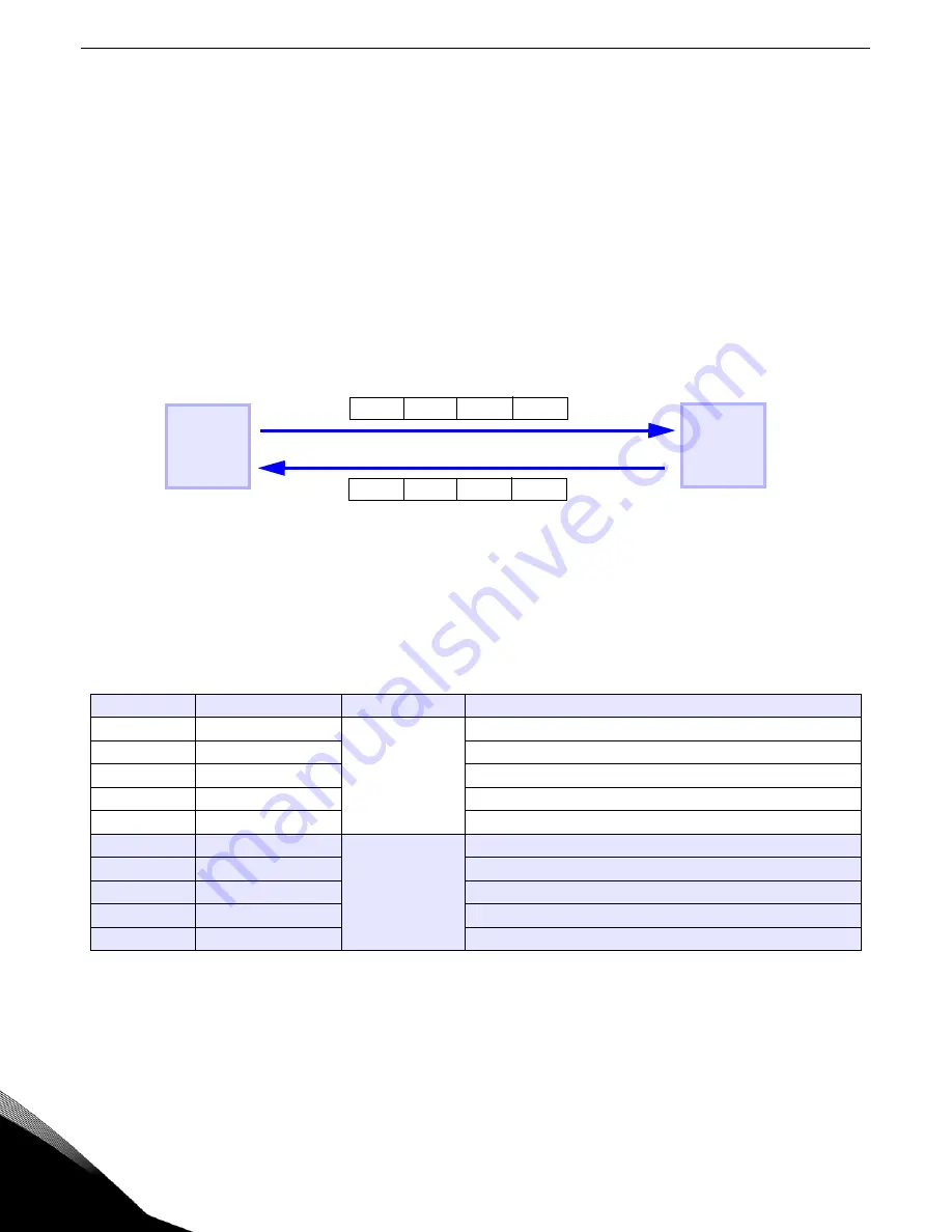
The polling message flow is shown in Figure 6.
Figure 6: Polling Message Diagram
I/O messages 20, 21, 70, and 71 are standard Common Industrial Protocol (CIP) assemblies.
I/O messages 121, 122, 131, 132, 171, 172, 181, and 182 are vendor-specific messages that allow for customized
assemblies.
The values of the following parameters indicate which drive parameters are read or written to by the I/O assembly:
Examples 1 and 2 on the following pages show how using the FBus Write 2 = Parameter 402 would allow the I/O
assembly to set the drive’s acceleration rate.
Table 5: Parameter Assignments (Parameters 880-894)
Parameter #
Parameter Name
Range
Default
880
FBus Read 1
0-65535
103 (Output Voltage)
881
FBus Read 2
104 (Output Current)
882
FBus Read 3
105 (Drive Load)
883
FBus Read 4
107 (Drive Temp)
884
FBus Read 5
909 (DI Status)
890
FBus Write 1
0-65535
103 (Output Voltage)
891
FBus Write 2
104 (Output Current)
892
FBus Write 3
105 (Drive Load)
893
FBus Write 4
107 (Drive Temp)
894
FBus Write 5
909 (DI Status)
Master
Slave
X5
Data (Output Assembly)
Data (Input Assembly)
Phone: 800.894.0412 - Fax: 888.723.4773 - Web: www.clrwtr.com - Email: [email protected]


