background image

Description of parameters 

vacon • 37 

24-hour s358 (0)40 837 1150 • Email: [email protected] 

t = Par. ID508

t

par. ID515

NX12K23

Motor speed

Output frequency

DC-braking

RUN
STOP

fout


ID509 ID510

NX12K33

Reference [Hz]

Output

frequency [Hz]


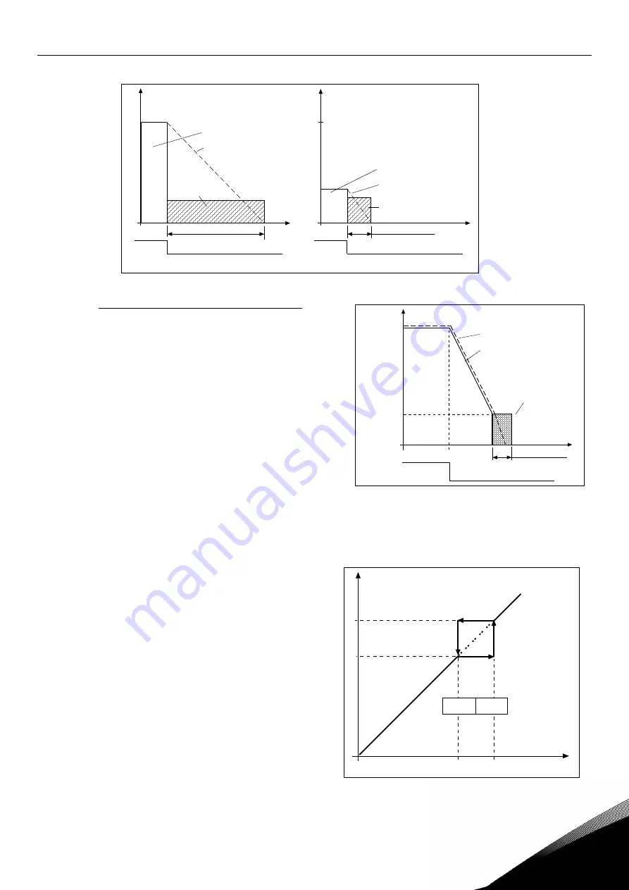
Figure 14. DC-braking time when Stop mode = Coasting. 

Par. ID506 = 1; Stop function = Ramp: 
 

After the Stop command, the speed of the 
motor is reduced according to the set decel-

eration parameters, as fast as possible, to the 
speed defined with parameter 

ID515

where the 

DC-braking starts. 
 

The braking time is defined with parameter 
ID508. If high inertia exists, it is recommended 
to use an external braking resistor for faster 

deceleration. See Figure 15. 
 

Figure 15. DC-braking time when Stop mode = 

Ramp 

509  

Prohibit frequency area 1; Low limit  

(2.5.1)


510 

Prohibit frequency area 1; High limit  

(2.5.2) 

In some systems it may be necessary to avoid 

certain frequencies because of mechanical 
resonance problems. With these parameters 

it is possible to set limits for the "skip fre-
quency" region. See Figure 16. 


Figure 16. Example of prohibit frequency area setting. 

fn

fn

t

t

t = 1 x Par. ID508

t = 0,1 x Par. ID508

NX12K21

0,1 x fn

RUN

STOP

RUN

STOP

Output frequency

Motor speed

Output frequency

Motor speed

DC-braking ON

DC-braking ON

fout

fout


Содержание NXP

Страница 1: ...heat exchanger application manual nx liquid cooled frequency converters...

Страница 2: ...4 15 3 6 Prohibit frequency parameters Control keypad Menu M2 G2 5 15 3 7 Motor control parameters Control keypad Menu M2 G2 6 16 3 8 Protections Control keypad Menu M2 G2 7 17 3 9 Autorestart parame...

Страница 3: ...f the temperature for the regulation comes from a sensor called FSA11 This is a type of flow switch that measures both the temperature of the coolant and the flow in the pipes If there is not enough f...

Страница 4: ...nd for reference and controls 14 DIN4 Pump 1 Forced or single run Combined with DIN1 15 DIN5 Pump 2 Forced or single run Combined with DIN1 16 DIN6 Sequence 2 pump system Combined with DIN1 17 CMB Com...

Страница 5: ...ignals as well as statuses and measurements Monitoring values cannot be edited See the product s user s manual for more information Code Parameter Unit ID Description V1 1 Output frequency Hz 1 Output...

Страница 6: ...Word 2 1173 General fault word V1 23 7 Warning Word 1 1174 General warning word V1 23 8 Fault Word 10 1202 Heat exchanger specific faults V1 23 9 Warning Word 10 1269 Heat exchanger specific warnings...

Страница 7: ...or PC communication F52 b12 Fieldbus communication F53 b13 b14 Slot communication F54 b15 4 mA F50 Table 5 Fault Word 1 3 1 1 4 Fault Word 2 ID1173 Description Comment b0 Output phase F11 b6 External...

Страница 8: ...2 Description Comment b0 b1 b2 b3 b4 b5 Over temperature F85 warning b6 b7 Inlet pressure low F88 b8 Flow F87 Table 8 Fault Word 10 3 1 1 7 Warning Word 10 ID1269 Description Comment b0 b1 b2 b3 Inlet...

Страница 9: ...1 7 Nominal frequency of the motor 30 00 320 00 Hz 50 00 111 Check the rating plate of the motor P2 1 8 Nominal speed of the motor 300 20 000 rpm 1440 112 The default applies for a 4 pole motor and a...

Страница 10: ...l range 0 1 1 390 0 Signal range 0 20mA 1 Signal range 4 20mA P2 2 11 AI2 supervision 0 1 1 1545 P2 2 12 AI2 custom minimum setting 0 00 P2 2 6 0 00 391 P2 2 13 AI2 custom maximum setting 0 00 100 00...

Страница 11: ...verted 1 Inverted P2 3 1 4 Analogue output 1 minimum 0 1 1 310 0 0 mA 1 4 mA P2 3 1 5 Analogue output 1 scale 10 1000 100 311 Table 12 Analogue output 1 signals 3 4 2 Analogue output 2 Code Parameter...

Страница 12: ...tering P2 3 3 3 Analogue output 3 inversion 0 1 0 1537 0 Not inverted 1 Inverted P2 3 3 4 Analogue output 3 minimum 0 1 0 1538 0 0 mA 1 4 mA P2 3 3 5 Analogue output 3 scale 10 1000 100 1539 Table 14...

Страница 13: ...ing OK 18 Alarm latched P2 3 5 3 Relay output 2 inversion 0 1 0 1541 0 Not inverted 1 Inverted Table 16 Relay output 2 signals 3 4 6 Relay output 3 Code Parameter Min Max Unit Default Cust ID Note P2...

Страница 14: ...lay output 6 Code Parameter Min Max Unit Default Cust ID Note P2 3 9 1 Relay output 6 signal selection A 1 1573 P2 3 9 2 Relay output 6 function 0 18 3 1567 0 Not used 1 Ready 2 Run 3 Fault 4 Fault in...

Страница 15: ...5 P2 4 6 DC braking time at start 0 00 600 00 s 0 00 516 0 DC brake is off at start P2 4 7 Flux brake 0 1 0 520 0 Off 1 On P2 4 8 Flux braking current 0 4 x IH 2 x IH A IH 519 Table 21 Drive control p...

Страница 16: ...0 00 Hz 50 00 602 P2 6 4 Voltage at field weakening point 10 00 200 00 100 00 603 n x Unmot P2 6 5 U f curve midpoint frequency 0 00 par P2 6 4 Hz 50 00 604 P2 6 6 U f curve midpoint voltage 0 00 100...

Страница 17: ...speed 0 0 150 0 40 0 706 P2 7 10 Motor thermal time constant 1 200 min Varies 707 P2 7 11 Motor duty cycle 0 100 100 708 P2 7 12 Stall protection 0 3 1 709 See par ID700 P2 7 13 Stall current 0 1 InMo...

Страница 18: ...P2 9 2 PID reference 0 2 0 332 0 PID ref from Keypad control page par 3 4 1 PID ref from Keypad control page par 3 5 2 PID ref from fieldbus ProcessDataIN 1 P2 9 3 Actual value 1 selection 0 2 1 334 0...

Страница 19: ...essure fault limit 0 00 100 00 bar 2 00 1571 P2 10 6 Coolant inlet pressure supervision 0 1 0 1569 0 Off No sensor 1 On Sensor installed P2 10 7 Temperature sensor minimum value 0 00 Par 2 10 7 C 0 00...

Страница 20: ...a out 3 selection 0 10000 45 854 Choose monitoring data with parameter ID P2 11 4 Fieldbus data out 4 selection 0 10000 1511 855 Choose monitoring data with parameter ID P2 11 5 Fieldbus data out 5 se...

Страница 21: ...Stop button 0 1 1 114 0 Limited function of Stop button 1 Stop button always enabled R3 4 PID reference Par 2 10 6 Par 2 10 7 C 25 00 R3 5 PID reference 2 Par 2 10 6 Par 2 10 7 C 0 00 Table 29 Keypad...

Страница 22: ...e from the zero frequency to the set maximum frequency par ID102 105 Preset speed 1 2 1 15 Parameter values are automatically limited between the minimum and maximum frequencies par ID101 ID102 107 Cu...

Страница 23: ...n be used in applications with constant motor load such as fans pumps etc 109 U f optimisation 2 1 13 Automatic torque boost The voltage to the motor changes automatically which makes the motor produc...

Страница 24: ...Use external cooling for the motor if the temperature tends to rise too high 110 Nominal voltage of motor 2 1 6 Find this value Un on the rating plate of the motor This parameter sets the voltage at...

Страница 25: ...the controller output to change by 10 00 s If the parameter value is set to 0 00 s the PID controller will operate as PD controller See examples at parameter ID132 below 120 Motor cos phi 2 1 10 Find...

Страница 26: ...ontroller function as I controller Example 2 Given values Par 2 1 12 P 100 Par 2 1 13 I time 1 00 s Par 2 1 14 D time 1 00 s Min freq 0 Hz Error value setpoint process value 10 Max freq 50 Hz As the p...

Страница 27: ...ss value 10 s Max freq 50 Hz As the error value increases also the PID output increases according to the set values D time 1 00s Figure 5 PID output with the values of Example 3 163 PID activation 2 9...

Страница 28: ...Contact closed Start of motor enabled 6 Preset speed 7 DC braking command Contact closed In Stop mode the DC braking operates until the contact is opened Figure 6 DIN3 as DC brake command input a Sto...

Страница 29: ...1 filter time 2 3 1 2 Defines the filtering time of the analogue output signal Setting this parameter value 0 will deactivate filtering 309 Analogue output 1 inversion 2 3 1 3 Inverts the analogue ou...

Страница 30: ...reference 12 Motor regulator activated Overvoltage or overcurrent regulator was activated 13 Output frequency limit supervision The output frequency goes outside the set super vision low limit high l...

Страница 31: ...taIN1 334 Actual value selection 2 9 3 0 AI1 control board 1 AI2 control board 2 Fieldbus FBProcessDataIN2 336 Actual value 1 minimum scale 2 9 7 Sets the minimum scaling point for Actual value See Fi...

Страница 32: ...gnal is activated Long filtering time makes the regulation response slower See Figure 10 Figure 10 AI1 signal filtering 379 AI1 signal range 2 2 3 0 Signal range 0 20 mA 1 Signal range 4 20 mA 2 Signa...

Страница 33: ...100 0 Min Max ID380 ID381 NX12K71 AO signal AI1 ID379 0 AI1 0 20mA Figure 11 AI1 no signal inversion If this parameter 1 inversion of analogue signal takes place 100 0 Min Max ID380 ID381 NX12K73 AO s...

Страница 34: ...ion of parameters Tel 358 0 201 2121 Fax 358 0 201 212 205 391 AI2 custom setting minimum 2 2 11 392 AI2 custom setting maximum 2 2 12 See parameters ID380 and ID381 398 AI2 signal inversion 2 2 13 Se...

Страница 35: ...external brake resistor This enables the frequency converter to decelerate the load with a torque equal to that of acceleration provided that the correct brake resistor has been selected See separate...

Страница 36: ...arameters If the regenerated energy is high it may be necessary to use an external braking resistor for faster deceleration 507 DC braking current 2 4 3 Defines the current injected into the motor dur...

Страница 37: ...me is defined with parameter ID508 If high inertia exists it is recommended to use an external braking resistor for faster deceleration See Figure 15 Figure 15 DC braking time when Stop mode Ramp 509...

Страница 38: ...D509 and ID510 The ramping speed selected acceleration deceleration time 1 or 2 is multiplied with this factor E g value 0 1 makes the acceleration time 10 times shorter than outside the prohibit freq...

Страница 39: ...put frequency at which the output voltage reaches the set ID603 maximum value 603 Voltage at field weakening point 2 6 4 Above the frequency at the field weakening point the output voltage remains at...

Страница 40: ...nd the application will not tolerate this over undervoltage In this case the regulator controls the output frequency taking the supply fluctuations into account 0 Controller switched off 1 Controller...

Страница 41: ...can also be programmed into relay outputs RO1 or RO2 702 Output phase supervision 2 7 5 0 No response 1 Warning 2 Fault stop mode after fault according to ID506 3 Fault stop mode after fault always by...

Страница 42: ...ter does not affect the maximum output current of the drive which is determined by parameter ID107 alone Figure 18 Motor thermal current IT curve 707 Motor thermal protection Time constant 2 7 10 This...

Страница 43: ...all time counter 710 Stall current limit 2 7 13 The current can be set to 0 0 2 IH For a stall stage to occur the current must have exceeded this limit See Figure 20 The software does not allow enteri...

Страница 44: ...ID102 For a stall state to occur the output frequency must have remained below this limit 713 Underload protection 2 7 16 0 No response 1 Warning 2 Fault stop mode after fault according to ID506 3 Fa...

Страница 45: ...to parameter ID713 If the drive is stopped the under load counter is reset to zero See Figure 23 Figure 23 Underload time counter function 717 Automatic restart Wait time 2 8 1 Defines the time befor...

Страница 46: ...2 Fault stop mode after fault according to ID506 3 Fault stop mode after fault always by coasting The input phase supervision ensures that the input phases of the frequency converter have an approxima...

Страница 47: ...ed 1 Warning if actual value falls below the limit set with par ID736 2 Warning if actual value exceeds the limit set with par ID736 3 Fault if actual value falls below the limit set with par ID736 4...

Страница 48: ...ese parameters Some typical values 1 Output frequency 15 Digital inputs 1 2 3 statuses 2 Motor speed 16 Digital inputs 4 5 6 statuses 3 Motor current 17 Digital and relay output statuses 4 Motor torqu...

Страница 49: ...ge in bar 1509 Temperature sensor minimum value 2 10 6 1510 Temperature sensor maximum value 2 10 7 1513 Relay output 2 function 2 3 5 2 See Table 30 at parameter ID313 1514 Constant speed 2 10 1 The...

Страница 50: ...ameters 0 no inversion of the respective relay output signal takes place 1544 Analogue input 1 supervision 2 2 4 1545 Analogue input 2 supervision 2 2 10 1546 Analogue input 3 supervision 2 2 17 The s...

Страница 51: ...t pressure alarm limit 2 10 4 When the inlet pressure drops below the limit set with this parameter a warning is instigated A pressure sensor must be installed in the system 1572 DIN6 function 2 2 3 T...

Страница 52: ...rval 2 10 11 After the expiry of the time defined with this parameter the autochange function takes place The available time range for the autochange varies from 1 to 168 hours 0 Test mode Autochange...

Страница 53: ...formation Run Stop direction and reference 123 Keypad direction 3 3 0 Forward The rotation of the motor is forward when the keypad is the active control place 1 Reverse The rotation of the motor is re...

Страница 54: ...one 44 0 1455 611 515 fax 44 0 1455 611 517 Italy Vacon S p A Via F lli Guerra 35 42100 Reggio Emilia telephone 39 0522 276811 fax 39 0522 276890 The Netherlands Vacon Benelux BV Weide 40 4206 CJ Gori...

Отзывы: