


SU640CSX
4110-0462, Rev. B
Page 57 of 97
© 2016 UTC Aerospace Systems
Date Printed: 1-Dec-2016
This document does not contain any export controlled technical data.
5.11.4.
Get Frame Period
Description
Gets FRAMEPERIOD, which controls the frame period (see
equation).
Setting Type
Operational
Command FRAME:PERIOD?
Parameters none
Return Values
value
Range
1 to 16777214
Type unsigned
integer
Example
FRAME:PERIOD? -- query command
366610 -- return value
5.12.
Trigger Commands
The user can change the trigger mode via the serial communication ASCII command TRIG:MODE,
which will allow control of the camera timing via 3.3V CMOS Logic signals.
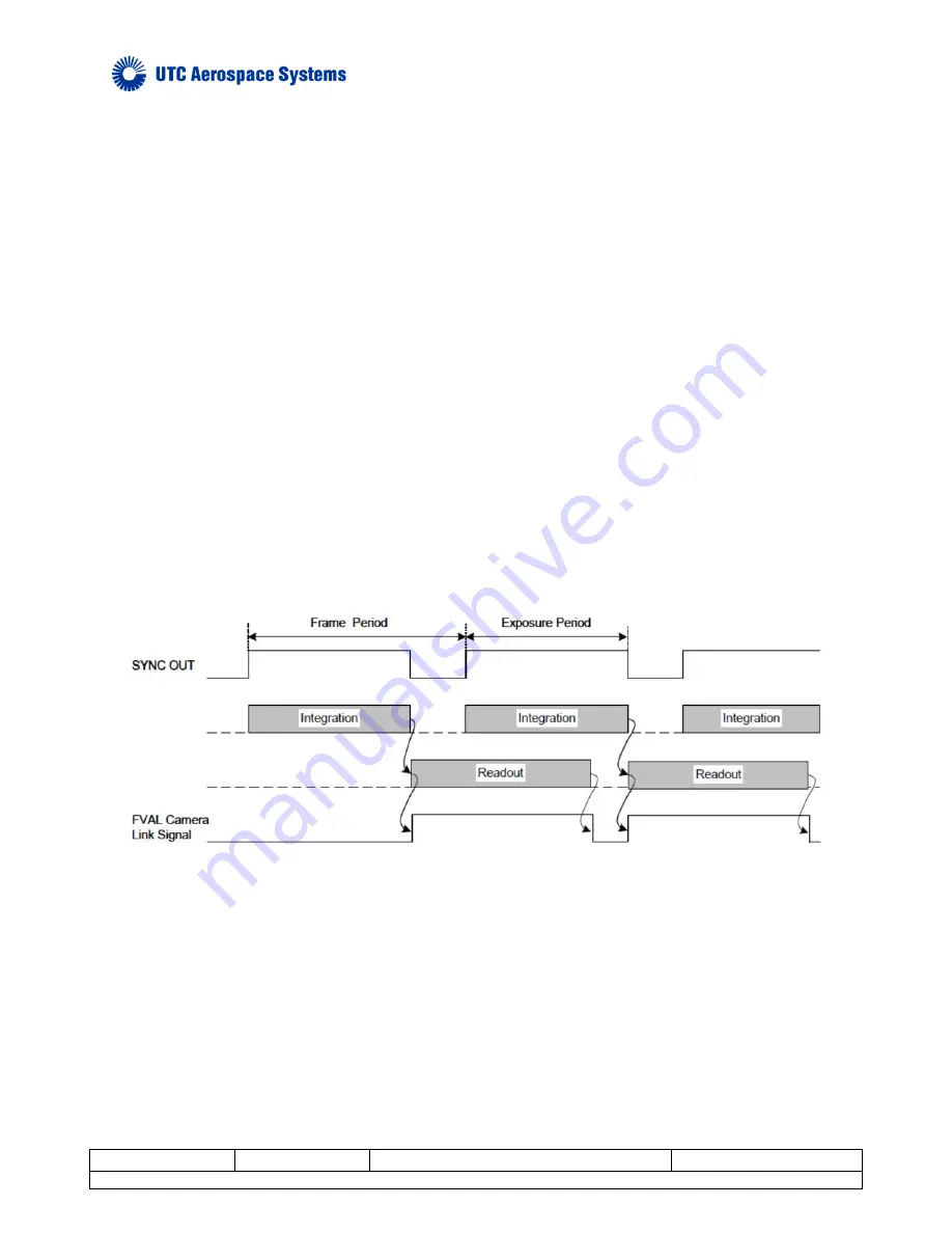
When trigger mode 0 is selected, the camera is free-running with the exposure and frame rate internally
timed. See Section 5.11 for description of commands to control the internally timed exposure and frame
period parameters. When in trigger mode 0, the timing sequence of the camera is as shown in the Figure.
In trigger mode 1, an external trigger timing signal is used to control the exposure and readout timing. An
external trigger timing signal can be applied to the camera through the Camera Link CC1 signal. The
signal source can be selected via the serial communication ASCII command TRIG:SOURCE. The
polarity of the trigger sources can be selected via the serial communication ASCII command TRIG:POL.
A latency time delay of 5 - 6 clocks is possible due to the shape and impedance of the incoming trigger,
and not added into the following discussion.
Figure 14. Trigger Mode 0 Freerun timing sequence


