P/N 466-5226-EMEA-
ML • REV B • ISS 09MAY16
3 / 26
Note:
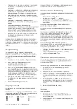
The device should be powered down while positioning
the input selection jumper.
External contact wiring
Use the following specifications for the external contact:
•
Maximum wire length: 30 m
•
Stranded,
Ø0.5–1.0 mm (24–18 AWG)
•
Hermetically sealed external switches (sealed reed switch)
that supply a minimum 500 milliseconds open or close on
alarm
External contacts and one internal reed switch may be used at
the same time.
You can connect up to five external contacts in series.
You can wire the terminal blocks on the sensor with leads from
an external contact. Contact includes both alarm and tamper
indication. The external contact is wired with two end-of-line
(EOL) resistors: one in series with and one across the external
contact (Figure 5, item 2).
EOL resistors must be installed at the external detection device
for proper supervision. This gives the following readings for a
normally closed configuration:
•
Open/short: Tamper or external contacts are not used
•
1 R (4.7
kΩ): All devices closed (one EOL)
•
2 R (9.4
kΩ): Alarm (both EOL)
Verifying RF communication
Before mounting the sensor, verify that the sensor mounting
location provides good RF communications to the panel.
To verify, do the following:
1. Put the panel/receiver into sensor test mode.
2. Take the sensor to the mounting location.
3. Hold the magnet next to the arrow on the end of the
sensor and then pull the magnet away from the sensor.
4. Listen for panel beeps to determine appropriate response
(refer to the specific panel/receiver documentation).
5. Exit sensor test mode.
Mounting
To mount the sensor:
1. Mount the sensor base with two 3.5 x 25mm pan head
screws at the T and L mounting hole locations (Figure 6).
2. Start both the T and L screws and turn down about
halfway.
3. Level and tighten the L screw first.
4. Tighten the T screw last. Do not over tighten the T screw.
5. Remove the magnet from its base.
6. Line up the arrow on the magnet with the small notch on
the side of the sensor (Figure 7), depending on the
internal reed switch being used (Figure 4).
7. Mount the magnet base with the 3.5 x 16 mm pan head
screws no more than 1 cm away from the sensor base.
Replace the magnet cover.
8. Attach the sensor cover to the sensor base and secure
with the 2.9 x 6.5mm pan head screw (Figure 2).
Battery replacement
When the system indicates that the sensor battery is low,
replace it immediately. Use the recommended replacement
batteries (see
“Specifications” below) or contact technical
support for more information.
To replace the batteries:
1. Remove the sensor cover (Figure 2).
2. Remove the battery and dispose as required by local laws.
3. Insert the replacement battery, observing correct polarity
(Figure 3).
4. Test sensor with the panel. See
Specifications
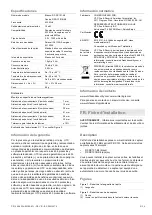
Model number
White: RF-DC101-K4
Mahogany: RF-DC101B-K4
Frequency
433 MHz
Maximum power output
10 mW
Compatibility
Interlogix 433 MHz control panels /
receivers with 80Plus protocol
Battery type
3.0 V, 1300 mAh lithium
Recommended batteries Duracell DL123A, Energizer EL123AP
Estimated battery life
>5 years with supervisory signals every
15 minutes and 4 activations per hour
Supervisory interval
Less than 20 minutes
Standby current
1.5 µA at 3 V
Maximum current
70 mA at 3 V
Battery low warning
2.65 V
Operating temperature
−10 to +55°C
Storage temperature
−34 to +60°C
Relative humidity
0 to 93% noncondensing
Dimensions (LxWxD)
101 x 31 x 28 mm
Weight
59 g
Distances
Mounted on non-ferromagnetic material:
Approach distance X (switch closed)
7 mm
Removal distance X (switch open)
13 mm
Approach distance Z (switch closed)
30 mm
Removal distance Z (switch open)
41 mm
Approach distance Y (switch closed)
20 mm
Removal distance Y (switch open)
30 mm
Tolerance for all distances
± 10%
For X, Y, Z distance explanation, see Figure 2.
Warranty information
To the extent permitted by law, UTC hereby disclaims all
warranties and representations, whether express or implied,
statutory or otherwise including (but not limited to) any
Содержание interlogix RF-DC101 Series
Страница 26: ...26 26 P N 466 5226 EMEA ML REV B ISS 09MAY16 ...


