


Installation Manual
Troubleshooting
560-0405-00 Rev –
December 14, 2001
Page 55
© 2001 by UPS Aviation Technologies Inc.
The second line is used to display the state of the altitude compare input, either “on” or
“off”.
The third line is used to display the state of the synchro #1 valid flag input, either “valid”
or “Invalid”.
The fourth line is used to display the state of the synchro #2 valid flag input, either
“valid” or “Invalid”.
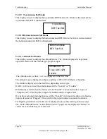
Discrete Inputs Page 3:
The top line is used to display the state of the air/ground #1 input, either “air” or “gnd”.
The second line is used to display the state of the air/ground #2 input, either “air” or
“gnd”.
9.2.6
External Interfaces
The external interfaces group is used to display the status of the rear panel interface in-
puts, such as the altitude and control panel inputs.
9.2.6.1
ADC Altitude Inputs
This page is used to display the altitude and status from the air data computer inputs.
The data is displayed for both the #1 and #2 inputs.
The altitude is displayed in feet, with 1 foot resolution.
The status of the input is displayed on the bottom line as:
•
Valid
•
Invalid (invalid status on 429 input data)
•
No data (no 429 altitude input data)
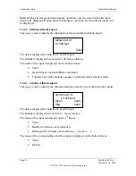
Air/Gnd #1:
air
Air/Gnd #2:
gnd
EXTERNAL INTER-
FACES
Press
←→↑↓
TEST
429 Alt #1
15,475 feet
Valid
Содержание AT7000
Страница 1: ...AT7000 Mode S Transponder Installation Manual December 14 2001 560 0405 00 Rev ...
Страница 4: ...Installation Manual AT7000 Mode S Transponder 560 0405 00 Rev December 14 2001 NOTES ...
Страница 75: ......
Страница 76: ......


