Installation Manual
Installation
560-0405-00 Rev –
December 14, 2001
Page 25
© 2001 by UPS Aviation Technologies Inc.
To compute the cable delay:
1.
Calculate the difference in cable lengths between the top and bottom antennas in
feet.
2.
Determine the cable delay: difference in length x 2 x 1.54 nsec/ft.
3.
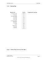
Select the coding and make the connections to the antenna delay program pins.
4.
Select the top or bottom code: connect TP 3C to common if the top antenna coax is
longer than the bottom.
3.4.7
Antenna Program
This program pin is used to identify installations in which only the bottom antenna is
used.
Ground
single bottom mount antenna installation
Open
dual antenna installation
3.4.8
Antenna BITE Program
This program pin is used to enable the antenna BITE test. Antennas capable of the BITE
test will have a DC path to ground. If enabled, the transponder will perform a continuity
test to verify the antenna is connected.
Ground
enable antenna BITE test
Open
disable antenna BITE test
3.4.9
Altitude Type Selection
The transponder is capable of using altitude data from one of four types. The altitude type
used is programmed by making the connections as defined in the following table.
Table 6 - Altitude Type Selection
Program Pins
Data Source
MP 6F
MP 6G
429 Data
Open
Open
Synchro Data
Open
Common
Gillham Data
Common
Common
Common Pin
MP 6H
3.5
Interface Connections
3.5.1
Discrete I/O Levels
3.5.1.1
Discrete Inputs
The discrete inputs have the following logic level thresholds:
Ground .................. < 3.5 volts DC or a resistance of < 10 ohms to ground
Open...................... > 18 volts DC or a resistance of > 100K to ground
Содержание AT7000
Страница 1: ...AT7000 Mode S Transponder Installation Manual December 14 2001 560 0405 00 Rev ...
Страница 4: ...Installation Manual AT7000 Mode S Transponder 560 0405 00 Rev December 14 2001 NOTES ...
Страница 75: ......
Страница 76: ......


