Installation
Installation Manual
Page 22
560-0405-00 Rev –
December 14, 2001
© 2001 by UPS Aviation Technologies Inc.
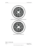
Figure 10 – Bottom Plug Connector Layout
Bottom
Plug
12
Suppression
Pulse Input
13
(int. conx
to pin 12)
Suppression
Pulse Input
11
Chassis
Ground
(Aircraft DC
Ground)
9
Not Used
1
115 v AC
power input
Hot
2
Not Used
3
28VDC
Power Input
Return
(-)
7
115 vac
Power
Input
Return
8
Signal
Ground
(Aircraft DC
Ground)
6
Not Used
5
Not Used
4
Not Used
10
28 VDC
Power Input
(+)
Содержание AT7000
Страница 1: ...AT7000 Mode S Transponder Installation Manual December 14 2001 560 0405 00 Rev ...
Страница 4: ...Installation Manual AT7000 Mode S Transponder 560 0405 00 Rev December 14 2001 NOTES ...
Страница 75: ......
Страница 76: ......

