


Installation
Installation Manual
Page 30
560-0405-00 Rev –
December 14, 2001
© 2001 by UPS Aviation Technologies Inc.
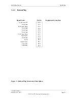
3.6
Data Loader Interface
Table 7 - Data Loader Plug
Reference
Section
Signal Name
Pin No.
Equipment Connection
2.5
Portable Data Loader (PDL) ARINC 615 Input Bus
A
B
1
2
429 Input (Provisions Only)
429 Input (Provisions Only)
Spare
3
Spare
4
Chassis Ground (429 Input Bus Shield) GND
5
Shield Ground
Spare
6
Spare
7
PDL ARINC 615 Output Bus
A
B
8
9
429 Output (Provisions Only)
429 Output (Provisions Only)
Spare
10
Spare
11
Spare
12
Spare
13
Spare
14
Spare
15
Chassis Ground (429 Output Bus Shield) GND
16
Shield Ground
Spare
17
Spare
18
Spare
19
115 Volt AC Power Input HOT
20
Chassis Ground GND
21
115 Volt AC Power Input COMMON
22
Spare
23
Spare
24
Spare
25
Spare
26
Spare
27
Spare
28
Spare
29
Spare
30
Spare
31
Spare
32
Spare
33
Содержание AT7000
Страница 1: ...AT7000 Mode S Transponder Installation Manual December 14 2001 560 0405 00 Rev ...
Страница 4: ...Installation Manual AT7000 Mode S Transponder 560 0405 00 Rev December 14 2001 NOTES ...
Страница 75: ......
Страница 76: ......


