background image

4.3.1  FINAL FOCUS LENS .................................................................27 
4.3.2  FOURTH MIRROR CLEANING................................................28 
4.3.3  THIRD MIRROR CLEANING ...................................................28 
4.3.4  SECOND MIRROR CLEANING................................................29 
4.3.5  BEAM WINDOW CLEANING ..................................................30 

4.4  TOP DOOR ADJUSTMENT .....................................................................30 
4.5  SET SCREW REPLACEMENT.................................................................31 
4.6  FIRST MIRROR CLEANING AND BEAM ALIGNMENT .....................32 
4.7  LASER REPLACEMENT..........................................................................37 
4.8  FIGURES FOR MAINTENANCE SECTION ...........................................39 

 
SECTION 5 - WARRANTY ...........................................................................................43 

 
5.1  ONE YEAR LIMITED WARRANTY .......................................................43 
5.2  IN-WARRANTY SERVICE ......................................................................44 
5.3  OUT-OF-WARRANTY SERVICE............................................................44 
5.4  REPACKAGING FOR SHIPMENT ..........................................................44 
5.5  FIELD SERVICE........................................................................................44 

 
APPENDIX A - DIP SWITCH SETTINGS TABLE ......................................................A1 
 
APPENDIX B - LASER SYSTEM SPECIFICATIONS .................................................B1 
 
APPENDIX C - LASER OPERATING PARAMETERS ...............................................C1 
 

Содержание ULS 1720C

Страница 1: ...OPERATIO A D MAI TE A CE MA UAL Model ULS 1720C Universal Laser Systems Inc 7707 East Acoma Drive Scottsdale AZ 85260 602 483 1214 Volume I Rev 5 April 1992...

Страница 2: ...RS 232 SERIAL CABLE CONFIGURATION 10 SECTION 3 OPERATION 11 3 1 BASIC OPERATING PROCEDURE 11 3 2 TURNING THE LASER SYSTEM ON 11 3 2 1 EMERGENCY OFF SWITCH 11 3 3 CONTROL PANEL LAYOUT 12 3 4 OPERATION...

Страница 3: ...31 4 6 FIRST MIRROR CLEANING AND BEAM ALIGNMENT 32 4 7 LASER REPLACEMENT 37 4 8 FIGURES FOR MAINTENANCE SECTION 39 SECTION 5 WARRANTY 43 5 1 ONE YEAR LIMITED WARRANTY 43 5 2 IN WARRANTY SERVICE 44 5 3...

Страница 4: ...the written permission of Universal Laser Systems Inc OTICE Universal Laser Systems Inc does not assume any liability arising out of the application or use of any products circuits or software descri...

Страница 5: ...ontroller providing a wide range of parameters for material processing Class I safety enclosure Fast X Y laser beam positioning system for quality laser processing at high speed Large material process...

Страница 6: ...of the system In the OFF position the shutter completely blocks the laser beam before it enters the work area Shutter control is located on the lower right corner of the system control panel When the...

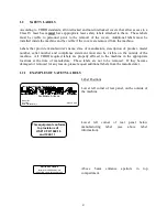
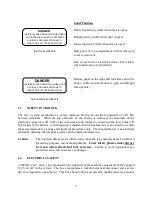
Страница 7: ...machine All CDRH required labels are properly affixed to the machine in the appropriate locations at the time of manufacture These labels are not to be removed If they become damaged or removed for a...

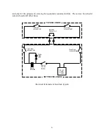
Страница 8: ...ock for testing and alignment procedures only The diagram below is an electrical schematic detailing the interlock system and the interlock defeat tool Caution The interlock defeat tool is utilized on...

Страница 9: ...closed at all other times 24 volt Power Supply Shutter Solenoid Shutter Control Switch Sutter Open LED Front Door Interlock Left Front Door Interlock Right Top Door Interlock Left Top Door Interlock...

Страница 10: ...em performs an automatic origin setting procedure and the arm and focusing optics carriage move Keep hands or objects out of the path of the arm optics carriage When not using the system unplug the po...

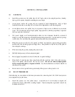
Страница 11: ...es until the enclosure can be pulled forward without obstruction c Carefully pull the enclosure forward and up until off of the machine Set the cover out of the way being careful not to scratch it 5 S...

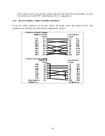
Страница 12: ...installed The system is set for a parallel connection at the factory This will work well with the majority of computers and software packages To change to a serial interface connection refer to the D...

Страница 13: ...ble must be used The diagram below describes the serial cable configuration required F G TxD RxD RTS CTS DSR S G DCD DTR 1 2 3 4 5 6 7 8 20 F G TxD RxD RTS CTS DSR S G DCD DTR 1 2 3 4 5 6 7 8 20 DCD R...

Страница 14: ...system To turn the system on press and release the green on switch To turn the system off press and release the red off switch Do not block movement of the motion system when turning the power on NOTE...

Страница 15: ...SE WIDTH RATE PULSE SELECT PROGRAM 1 2 3 4 5 6 7 8 X POSITION Y POSITION P P MODE 2 1 ENTER REPEAT REPEAT VIEW PAUSE P SPEED FAST AUX TEST SHUTTER OPEN CLOSED POWER Laser Control Keypad Processing Spe...

Страница 16: ...to manually mark lines on material to indicate the edges of the engraving field or as alignment marks VIEW KEY VIEW Pressing this key causes the focusing optics carriage to move to the upper right co...

Страница 17: ...mode will continue to store drawings until it is full the capacity is 1 megabyte If multiple drawings are stored in memory pressing the repeat key will cause all of the stored drawings to be processed...

Страница 18: ...c A dot will appear to the right of the pulse mode character in the laser control display when the laser is on see section 3 6 for details 3 5 SHUTTER CO TROLS The shutter controls are used to open an...

Страница 19: ...pful in identifying the best speed for a particular engraving or cutting job But if processing speed is being controlled by software speeds should not be adjusted manually during engraving 2 Computer...

Страница 20: ...digital control board This control board produces a square wave type signal which is essentially a sequence of on and off commands which cycle the laser at high speed The Laser Control keypad is used...

Страница 21: ...se rate is defined as the time that elapses between the start of one pulse and the start of the next pulse CPM may be used when engraving or marking materials such as coated metals where a higher degr...

Страница 22: ...isplay will start blinking b Enter new pulse rate data with number keys or edit with DELETE key then enter data c Press PULSE RATE key to set the new pulse rate 2 Repeat step 1 until all desired power...

Страница 23: ...s Many software packages also give the user the ability to assign a color or several colors to a pen If Microsoft Windows is being used the color pen number combinations are found in the ULS Windows P...

Страница 24: ...m below c Observe the top of the focus tool Now raise the Z axis stage by cranking the knob clockwise until the focus tool just starts to tilt away from the lens holder as shown in the diagram below B...

Страница 25: ...ailable from ULS 3 11 VIEW POSITIO I DICATOR A green dome light mounted on the top of the system just above the control panel will light up to indicate that the motion system is in the home position T...

Страница 26: ...nuals for the program being used ANSI B ISO A3 ISO A4 ANSI A Figure showing Field sizes superimposed on the engraving table Field Size Maximum Processing Area SW1 6 DIP Switch Settings SW1 7 SW1 8 420...

Страница 27: ...compartment of the system In the OFF position the shutter completely blocks the laser beam before it enters the work area Shutter control is located on the lower right corner of the system control pa...

Страница 28: ...he frame reference Figure 1 Also remove knob for Z stage table height adjustment b Tilt the front of the enclosure up approximately two to three inches until the enclosure can be pulled forward withou...

Страница 29: ...h tissues If large particles are present on the control panel dust the panel lightly with an oil free compressed air source before wiping with tissue as large particles will scratch the surface of the...

Страница 30: ...issue so that lens and spacers drop out onto lens tissue d Inspect lens spacers and clean if necessary with a swab and lens cleaner e Hold lens by edges using lens tissue and thoroughly dust off the l...

Страница 31: ...using the oil free compressed air or Freon duster as described previously If mirror is extremely dirty use a stream of lens cleaning solution 1 from the small plastic wash bottle to flush the surface...

Страница 32: ...pply lens cleaning solution 1 to the mirror Let sit for one minute f Using a cotton swab gently roll across mirror once g Use new swabs and repeat rolling across mirror once with each new swab until m...

Страница 33: ...ning solution 1 to the window using the sprayer bottle Let sit for one minute 4 Wet a cotton swab and gently wipe across window 5 Use new dry swabs and repeat wiping across window to dry 6 Inspect win...

Страница 34: ...t is necessary Typical symptoms of worn set screws are corners of objects do not connect or overshoot wiggly lines occur in either X Y or diagonal movement To replace set screws new set screws can be...

Страница 35: ...k each set screw off of the rail and repeat the adjustment procedure 2 X Axis a Move Y arm until centered in motion system b Open front door of system c Using a small jeweler s screwdriver remove the...

Страница 36: ...e moved forward with out obstruction c Carefully pull the enclosure forward and up until off of the machine Set cover out of the way being careful not to scratch it 3 With the top cover removed cut th...

Страница 37: ...mirror holder into shutter support with mirror surface towards front of machine and tighten set screws until mirror holder rotates with some friction 14 Realign optics as follows 16 The interlock defe...

Страница 38: ...friction and adjust mirror 1 by turning it one way or the other until a beam appears on the thermal paper If unable to obtain a beam increase the pulse width by 5 and attempt to find the beam again by...

Страница 39: ...center the marks horizontally move the block on which mirror 2 is mounted to one side or the other side usually a very small amount of movement is needed while keeping it square against the rail refer...

Страница 40: ...th a new piece a If marks are aligned but to the left or right of center looking from the front of the machine move the block on which mirror 2 is mounted to one side or the other side usually a very...

Страница 41: ...ck d Remove the six 10 32 socket head cap screws from the three retainer bars on side of the laser reference Figure 2 e From rear of machine slide laser left so fuse caps clear the left support bracke...

Страница 42: ...of laser h Carefully push green white and black wires of the power cable through grommet in vertical plate Push the wires through one at a time i Attach green white and black wires to the terminal bl...

Страница 43: ...s FIGURE 1 ENCLOSURE HOLD DOWN LOCATIONS UNIVERSAL LASER SYSTEMS Z Stage Knob Note Large arrows show correct path for installation and removal One of four screws to be removed Laser retaining bar FIGU...

Страница 44: ...4th Mirror Left Motion System Rail Thermal Paper 2nd Position Masking Tape 1st Position Masking Tape 2nd Position Focus Lens Holder see figure 1 Right Motion System Rail Install defeat tool here 3rd M...

Страница 45: ...Lens spacer Final focus lens lens spacer lens holder Thumb screw convex surface facing upward FIGURE 4 FOCUS LENS ASSEMBLY DETAIL Nylon Tipped Ball Plunger Set Screws Nylon Tipped Ball Plunger Set Sc...

Страница 46: ...on Tipped Ball Plunger Set Screws Y Bearing Y Rail Y Bearing Y Bearing Focus Lens Carriage Base Focus Lens Nylon Tipped Ball Plunger Set Screws Y Bearing Y Rail FIGURE 6 FOCUS LENS CARRIAGE SET SCREW...

Страница 47: ...rs All warranty work must be performed by ULS Universal Laser Systems reserves the right to request that the system be returned to the factory for repair or to provide on site repair During the warran...

Страница 48: ...cy The equipment must be packed for shipment per Section 5 4 A description of the problem along with the owner s name address telephone number and equipment serial number should be included The equipm...

Страница 49: ...46 For current information regarding field service call Universal Laser Systems Inc Scottsdale Arizona 602 483 1214...

Страница 50: ...TIN ISO GERMAN ISO SPANISH ANSI ASCII 2 ISO SWEDISH NAME ISO FRENCH ISO PORTUGUESE 9 10 ANSI A ANSI B ISO A3 ON OFF FRENCH GERMAN ISO NORWAY 1 ISO U K NOT USED SCANDINAVIAN ISO NORWAY 2 ISO ITALIAN NO...

Страница 51: ...rs DSW2 9 OFF sets the command mode to RD GL I This switch should always be in the OFF position The default switch positions set at the factory are as shown in the diagram below 1 2 3 4 5 6 7 8 9 10 O...

Страница 52: ...erial RS 232C Manual Speed Selection 8 Stage Commands HP GL RD GL1 Buffer Memory Size 1MB System Dimensions 37 x32 x21 System Weight 165 lbs Safety Classification Class I Support Table Dimensions 19 x...

Страница 53: ...the gray area Use the following procedure for choosing laser power parameters 1 Choose a processing speed and turn to the graph for that speed 2 Choose a pulse rate The pulse rate is shown in pulses p...

Страница 54: ...width for the speed and pulse rate chosen then the settings are fairly optimized and can be used If the pulse width which provides good results is much less than the maximum usable pulse width than t...

Страница 55: ...SPEED Anodized Aluminum See Applications ote 1 bleach anodize coating 125 39999 P 1 Enamel Coated Brass See Applications ote 4 remove enamel 2 3 passes 150 300 39999 P 1 Lycra See Applications ote 8 C...

Страница 56: ...Cut See Applications ote 14 800 39999 P 1 DAP Mark 80 90 19999 P 1 PVC Mark 200 8000 P 1 Vinyl 1 20 thousandths Mark 40 12500 P 1 Cut to Backing 50 100 20000 P 1 10 Cut through Backing 50 100 39999 P...

Страница 57: ...0 150 39999 P 1 Cut Approximately 1 8 per pass 800 1000 39999 P 1 Remove Fill 800 7000 P 1 Lexan Cut 20 40 thousandths 500 1000 39999 P 1 Avonite Mark 100 300 39999 P 1 Cut 100 1400 39999 P 1 Kapton S...

Страница 58: ...cut and brush Repeat two or more times for each side until wire is bare Make a final pass to clean up any residual teflon 14 When cutting very small stencils 1 8 or 0125 use a high resolution lens and...

Отзывы: