20
During normal operation the laser system will use the power setting which is currently displayed
on the control panel. To recall a different stored power setting for use, press in sequence the
program select key, the power setting number which contains the desired power setting, and the
store key.
3.8
SOFTWARE COTROLLED POWER CHAGE (OPTIOAL)
The ULS Laser Engraving Systems have the optional ability to accept software commands to
change power settings before and during engraving, which comes from the fact that the laser
systems emulate an HP-GL plotting device. The power setting numbers mentioned in section 3.6
are analogous to the pen numbers used in HP-GL to change pens on a plotter. A color in a
software package assigned a pen number will be processed using the corresponding stored power
setting. Once the power settings have been stored as described in section 3.6, accessing a power
setting using software is only a matter of assigning the appropriate color to a particular portion of
a drawing.
The color/pen number combinations vary between software packages and it is best to consult
your software manual to find out which colors correspond to which pen numbers. Many software
packages also give the user the ability to assign a color or several colors to a pen. If Microsoft
Windows is being used, the color pen/number combinations are found in the ULS Windows
Printer Driver. Use of the driver is explained in the documentation which comes with it. (The
ULS Windows Printer Driver is required if Windows is being used and can be purchased from
ULS.)
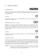
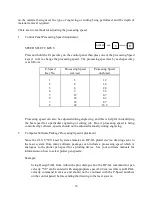
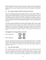
Turning the Power Change Option on and off:
Power Change ON
8
and
0
Power Change
OFF
9
and
0
The power change option can be turned on and off by pressing a sequence of keys. If the option
is turned off the machine will operate in manual mode as described in section 3.6. To turn the
option on, press in sequence the 0 and 8 keys and to turn the option off, press in sequence the 0
and 9 keys. A dot will appear on the display to the right of the program number to indicate that
the option is turned on.
3.9
FOCUSIG PROCEDURE
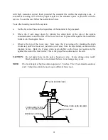
Laser processing should be done with the laser beam focused on the top surface of the work
piece. The focal length of the standard optics, provided with the system, is 2.5 inches. To find
the proper focus position for the work piece, measure the distance between the top surface of the
work piece and bottom of the focusing lens housing. Adjust the Z axis so the distance between
the two is 2.5 inches. The laser system can accomidate materials up to 10.5 inches (11.5 inches

