


UPS338-01-00 PowerWAVE 8000-RI DPA User Manual Dated 5 April 2013
3-23
3: Installation
3.12 Module interfacing facilities
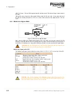
Figure 3.16 UPS interfacing connectors (front of the UPS cabinet)
The PowerWAVE 8000-RI DPA system contains a communications card, located on the lower front of the
UPS cabinet, which provides various I/O interface facilities.
Two LEDs (4) located on the board provide indication of the board’s status:
• Green LED – blinking twice per second indicates normal operation.
• Red LED – board alarm (indicates possible board replacement when lit).
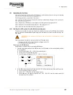
3.12.1 Smart Port JD1 (Serial RS 232) and USB Port
The SMART PORT is an intelligent RS 232 serial port that allows the UPS to be connected to a computer.
The connector is a standard D-Type, 9-pin, female, and the USB is a standard USB port.
When installed, the optional SMART PORT software, WAVEMON, this connection allows the computer to
monitor the mains voltage and the UPS-status continuously and display a message in the event of any UPS
system changes. Figure 3.17 and show the connection to a PC from the UPS for PC’s with a 9 pin serial port
and 25 pin serial port respectively.
Figure 3.17 Connector Cable - PC Serial Port
1
2
3
4
5
6
7
8
1
JR2 (RS485)
Not used.
2
X2
Customer interface on Phoenix Terminals (potential-free
contacts).
3
X1
Customer inputs.
4
LEDs
Interface Board Status LEDs.
5
JD1 (RS232)
Sub D9 female, PC Interface.
6
USB
PC Interface.
7
SLOT 2
Slot for optional SNMP card only.
8
SLOT 1
PowerReporter Slot for optional modem/ethernet card
only.
1
2
3
4
5
9
1
2
3
4
5
9
1
2
3
4
5
9
1
2
3
4
5
6
7
25
Interface Cable
UPS end
Interface Cable
Computer end
9-Pin D-Type
(Male)
9-Pin D-Type
(Female)
9-Pin D-Type
(Male)
25-Pin D-Type
(Female)
Interface Cable
UPS end
Interface Cable
Computer end
Содержание PowerWAVE 8000DPA RI
Страница 1: ...User Manual PowerWAVE 8000DPA RI Pioneering solutions for total power protection ...
Страница 2: ...UPS338 01 00 PowerWAVE 8000 RI DPA User Manual Dated 5 April 2013 ...
Страница 4: ...UPS338 01 00 PowerWAVE 8000 RI DPA User Manual Dated 5 April 2013 ...
Страница 8: ... iv UPS338 01 00 PowerWAVE 8000 RI DPA User Manual Dated 5 April 2013 ...
Страница 10: ...1 Safety 1 2 UPS338 01 00 PowerWAVE 8000 RI DPA User Manual Dated 5 April 2013 ...
Страница 16: ...2 General Description 2 6 UPS338 01 00 PowerWAVE 8000 RI DPA User Manual Dated 5 April 2013 ...
Страница 21: ...UPS338 01 00 PowerWAVE 8000 RI DPA User Manual Dated 5 April 2013 3 5 3 Installation RI 10 TYPE x1 Figure 3 2 ...
Страница 22: ...3 Installation 3 6 UPS338 01 00 PowerWAVE 8000 RI DPA User Manual Dated 5 April 2013 RI 11 TYPE1 Figure 3 3 ...
Страница 23: ...UPS338 01 00 PowerWAVE 8000 RI DPA User Manual Dated 5 April 2013 3 7 3 Installation RI 12 TYPE 2 Figure 3 4 ...
Страница 24: ...3 Installation 3 8 UPS338 01 00 PowerWAVE 8000 RI DPA User Manual Dated 5 April 2013 RI 20 TYPE x2 Figure 3 5 ...
Страница 25: ...UPS338 01 00 PowerWAVE 8000 RI DPA User Manual Dated 5 April 2013 3 9 3 Installation RI 22 TYPE3 Figure 3 6 ...
Страница 26: ...3 Installation 3 10 UPS338 01 00 PowerWAVE 8000 RI DPA User Manual Dated 5 April 2013 RI 24 TYPE 4 Figure 3 7 ...
Страница 27: ...UPS338 01 00 PowerWAVE 8000 RI DPA User Manual Dated 5 April 2013 3 11 3 Installation Figure 3 8 RI 40 Type X4 ...
Страница 28: ...3 Installation 3 12 UPS338 01 00 PowerWAVE 8000 RI DPA User Manual Dated 5 April 2013 Figure 3 9 RI 40 Type X4 ...
Страница 42: ...3 Installation 3 26 UPS338 01 00 PowerWAVE 8000 RI DPA User Manual Dated 5 April 2013 ...