


UPS338-01-00 PowerWAVE 8000-RI DPA User Manual Dated 5 April 2013
3-13
3: Installation
3.8
UPS Power Cabling (preparation and planning)
3.8.1 General
requirements
It is the customer’s responsibility to provide all external fuses, isolators and cables used to connect the UPS
input and output power supplies. The information provided in this section of the manual should assist in the
planning and preparation of the UPS power cabling.
The UPS input supply and bypass supply should be connected to the utility mains through a LV-Distribution
board, and protected by a circuit breaker or fuse. This provides overload protection and also a means of
isolating the UPS from the mains supply when required. Similarly, the UPS output supply should be
connected to the load equipment via a suitably fused output distribution panel.
The UPS can be wired with a ‘single feed’ input (standard), whereby the UPS input supply is connected
internally to the UPS bypass circuit; or it can be wired with a ‘dual feed’ input – where the UPS bypass circuit
is connected to a dedicated ‘bypass’ supply
(See Figure 3.11)
.
Figure 3.11 identifies the UPS input/output cabling requirements and provides information regarding the
necessary fuse and cable ratings and cable sizing.
Figure 3.12 shows details of the UPS power terminals’ location and sizing and illustrates that the UPS unit
requires the following power cables:
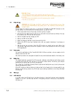
Input neutral grounding
Figure 3.10 Input neutral grounding
Key Point:
This information is given for guidance only and all fuses, isolators and power cables
must be rated and installed in accordance with the prescribed IEC standards or local regulation –
e.g. BS7671:2008.
Rectifier (In):
• three-phase (1L1, 1L2, 1L3)
• neutral (1N)
• protective earth (PE) connection for the rectifier input
Bypass (In):
• three-phase (2L1, 2L2, 2L3)
• neutral (2N)
• protective earth (PE) connection for the bypass if used as ‘Dual Feed’ input
Load (Out):
• three-phase (3L1, 3L2, 3L3)
• neutral (3N)
• protective earth (PE) connection for the load output
Battery:
• Plus (+)
• Common (N)
• Minus (-)
• protective earth (PE) connection for external batteries (where used)
Key Point:
Input neutral is required to operate the rectifier.
In TN-S systems, no 4-pole input switches or circuit breakers should be used.
During battery operation the neutral must always be grounded.
0V
230V
UPS
Содержание PowerWAVE 8000DPA RI
Страница 1: ...User Manual PowerWAVE 8000DPA RI Pioneering solutions for total power protection ...
Страница 2: ...UPS338 01 00 PowerWAVE 8000 RI DPA User Manual Dated 5 April 2013 ...
Страница 4: ...UPS338 01 00 PowerWAVE 8000 RI DPA User Manual Dated 5 April 2013 ...
Страница 8: ... iv UPS338 01 00 PowerWAVE 8000 RI DPA User Manual Dated 5 April 2013 ...
Страница 10: ...1 Safety 1 2 UPS338 01 00 PowerWAVE 8000 RI DPA User Manual Dated 5 April 2013 ...
Страница 16: ...2 General Description 2 6 UPS338 01 00 PowerWAVE 8000 RI DPA User Manual Dated 5 April 2013 ...
Страница 21: ...UPS338 01 00 PowerWAVE 8000 RI DPA User Manual Dated 5 April 2013 3 5 3 Installation RI 10 TYPE x1 Figure 3 2 ...
Страница 22: ...3 Installation 3 6 UPS338 01 00 PowerWAVE 8000 RI DPA User Manual Dated 5 April 2013 RI 11 TYPE1 Figure 3 3 ...
Страница 23: ...UPS338 01 00 PowerWAVE 8000 RI DPA User Manual Dated 5 April 2013 3 7 3 Installation RI 12 TYPE 2 Figure 3 4 ...
Страница 24: ...3 Installation 3 8 UPS338 01 00 PowerWAVE 8000 RI DPA User Manual Dated 5 April 2013 RI 20 TYPE x2 Figure 3 5 ...
Страница 25: ...UPS338 01 00 PowerWAVE 8000 RI DPA User Manual Dated 5 April 2013 3 9 3 Installation RI 22 TYPE3 Figure 3 6 ...
Страница 26: ...3 Installation 3 10 UPS338 01 00 PowerWAVE 8000 RI DPA User Manual Dated 5 April 2013 RI 24 TYPE 4 Figure 3 7 ...
Страница 27: ...UPS338 01 00 PowerWAVE 8000 RI DPA User Manual Dated 5 April 2013 3 11 3 Installation Figure 3 8 RI 40 Type X4 ...
Страница 28: ...3 Installation 3 12 UPS338 01 00 PowerWAVE 8000 RI DPA User Manual Dated 5 April 2013 Figure 3 9 RI 40 Type X4 ...
Страница 42: ...3 Installation 3 26 UPS338 01 00 PowerWAVE 8000 RI DPA User Manual Dated 5 April 2013 ...