UNIBLOC-PD Operation & Service Manual: PD200-576 29
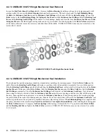
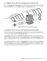
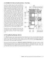
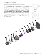
4.4.8 UNIBLOC 501 Series Seal Installation – Final Step
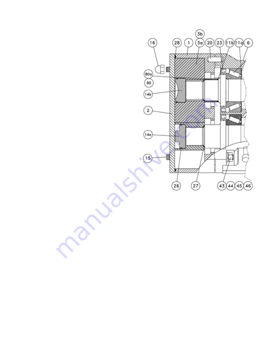
See section 5.3 for torque limits. If not part of the shaft seal as-
sembly, slide the plastic mounting sleeves over the splined ends
of the shafts. Slide on the rotor housing (1) tap it with a rubber
mallet to seat it properly on the dowel pins (20). Make sure the
alignment mark on the rotor housing lines up with the one on the
gearbox (6). The rotor housing must make firm contact with the
gearbox. Fasten the hex nuts (43) with the split washer (44) on
the stud ends and tighten in a cross pattern. Remove the plastic
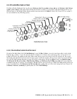
sleeves from the shaft ends. Slide the rotor shaft o-rings (27)
over the splined shaft ends and on the step, if applicable. One
rotor and one shaft have been marked with the same symbol.
Slide the rotors over the corresponding shafts and push them
making sure the o-rings seat properly. The rotors must make
contact with the shafts. Place o-rings (26) on the rotor bolts
(14a,14b). Lubricate them and the rotor bores. Place a nonmet-
al object between the rotors to keep them from turning. Thread
the rotor bolts into the shaft ends. Turn the drive shaft to make
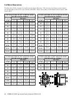
sure the rotors turn freely. Measure the clearances between the
rotor housing and the rotors. Compare these values with those
listed in section 5.4. If the measured clearances at positions 1-7,
8, and 10 are smaller than those listed, the rotors must be ground
and polished to achieve the correct values. If the measured
clearances at positions 9 and 11 are not within the tolerances
listed the shafts must be adjusted by disassembling the gearbox,
as instructed in section 3.0, and changing the shims (11a).
Place the front cover (2) and the o-ring (28) on the studs. Tight-
en the front cover nuts (16). Check the oil level in the gearbox
as described in section 5.2. The pump is now ready to be in-
stalled in the system. Refer to section 2.3 before starting the
pump.
4.5 Pump Bearing Housing Service
The
UNIBLOC
bearing housing is supplied permanently lubricated with nitrile seals. However, for certain applications and at the
user’s request, drain plugs and a vent will be supplied. The oil level should be checked at regular intervals and the seals should be
changed once per year or after 2000 hours of service, whichever occurs first. When applications exceed constant service temper
-
atures of 1800C (3560F) a vent and high temperature lubricant must be used. For such cases, contact
UNIBLOC-PUMP
or an
authorized service center for an adequate service schedule.
Before proceeding with the following steps,
DISENGAGE POWER TO THE MOTOR
. If the pump is connected to piping,
depressurize the system and close valves on both the suction and discharge sides to isolate the pump from the rest of the system.
Disconnect the piping and remove the pump from the system. Removal of the wet end of the pump (i.e. the cover, rotors, rotor
housing, and shaft seals) must be completed first before disassembly of the pump bearing housing. The method of removing these
parts is dependent upon the type of shaft seals the pump has and is outlined in section 4.4.
Содержание 54001010P20H6010T12E
Страница 42: ...42 UNIBLOC PD Operation Service Manual PD200 576 UNIBLOC PUMP ...
Страница 43: ...UNIBLOC PD Operation Service Manual PD200 576 43 UNIBLOC PUMP ...
Страница 44: ...44 UNIBLOC PD Operation Service Manual PD200 576 UNIBLOC PUMP ...
Страница 45: ...UNIBLOC PD Operation Service Manual PD200 576 45 UNIBLOC PUMP ...
Страница 46: ...46 UNIBLOC PD Operation Service Manual PD200 576 UNIBLOC PUMP ...
Страница 47: ...UNIBLOC PD Operation Service Manual PD200 576 47 UNIBLOC PUMP ...
Страница 48: ...48 UNIBLOC PD Operation Service Manual PD200 576 UNIBLOC PUMP ...
Страница 49: ...UNIBLOC PD Operation Service Manual PD200 576 49 UNIBLOC PUMP ...
Страница 50: ...50 UNIBLOC PD Operation Service Manual PD200 576 3 ...
Страница 51: ......
Страница 52: ......

