12 UNIBLOC-PD Operation & Service Manual: PD200-576
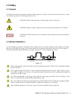
3.2 System Design
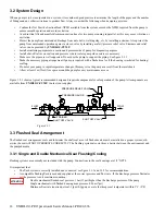
When a pump is to be incorporated in a system, it is considered good practice to minimize the length of the pipes and the number
of fittings and any other restrictions to product flow. Always consider the following when designing a system:
• Confirm the Net Positive Suction Head-NPSH available from the system exceeds the NPSH required from the pump to
ensure smooth operation and avoid cavitation.
• Avoid suction lifts and manifold/common suction lines for two pumps running in parallel, as this may cause vibration or
cavitation.
• Protect the pump from unintended blockage from nuts, bolts, welding slag, etc, by installing a strainer. Also protect the
pump from unintended operation against a closed valve by installing a safety/pressure relief valve. Strainers and relief
valves can be provided by
UNIBLOC-PUMP.
• Install monitoring equipment on suction and pressure side of pump for diagnostic purposes.
• Install shut-off valves on suction and pressure side to isolate pump when service is necessary.
• Make sure the pipes are well supported. Do not use the pump to support the piping. See figure 2.3.1
• Make the necessary piping arrangement if pump is supplied with a flushed seal or if the housing is jacketed for heating/
cooling.
• Do not expose pump to rapid temperature changes, this may seize the pump as a result from thermal shock.
• Allow at least 1m (3feet) free space around the pump for easy maintenance access.
Figure 3.2.1 shows a typical recommended design and required components for safe operation of the pump. All components are
available from
UNIBLOC-PUMP.
Contact your supplier.
3.3 Flushed Seal Arrangement
The flushed seal arrangement cools and lubricates the shaft seal area. All flushed seals must be installed in a proper system; oth
-
erwise the seal will NOT OPERERATE CORRECTLY. The flushing system also works as a barrier between the environment and
the pumped media.
3.3.1 Single and Double Mechanical Seal Flushing/Cooling
Flushing systems are normally not included with the pump. Connections to the seal housings are 1/8” NPTF.
It is important that:
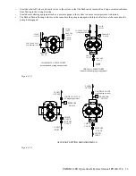
• The flush system is correctly installed and connected, see figure 3.3.1 and 3.3.2 for recommendations.
• A compatible flushing fluid is used and supplied at the correct pressure and flow rate. If the discharge pressure fluctuates
set the pressure to suit maximum condition.
Double mechanical flushed seal pressure: 1bar (15psi) higher than the discharge pressure of the pump
Single mechanical with flushed housing max pressure: 0.5bar (7psi)
Minimum flow rate required per seal: 1lpm (0.3gpm) or a rate that keeps seal temperature within 5°C (9°F)
PRESSURE RELIEF VALVE
SHUT OFF VALVE
STRAINER
PRESSURE GAUGE
FLOW
FLOW
SHUT OFF VALVE
Figure 3.2.1
ATTENTION
Содержание 54001010P20H6010T12E
Страница 42: ...42 UNIBLOC PD Operation Service Manual PD200 576 UNIBLOC PUMP ...
Страница 43: ...UNIBLOC PD Operation Service Manual PD200 576 43 UNIBLOC PUMP ...
Страница 44: ...44 UNIBLOC PD Operation Service Manual PD200 576 UNIBLOC PUMP ...
Страница 45: ...UNIBLOC PD Operation Service Manual PD200 576 45 UNIBLOC PUMP ...
Страница 46: ...46 UNIBLOC PD Operation Service Manual PD200 576 UNIBLOC PUMP ...
Страница 47: ...UNIBLOC PD Operation Service Manual PD200 576 47 UNIBLOC PUMP ...
Страница 48: ...48 UNIBLOC PD Operation Service Manual PD200 576 UNIBLOC PUMP ...
Страница 49: ...UNIBLOC PD Operation Service Manual PD200 576 49 UNIBLOC PUMP ...
Страница 50: ...50 UNIBLOC PD Operation Service Manual PD200 576 3 ...
Страница 51: ......
Страница 52: ......


