background image

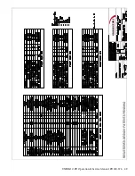
UNIBLOC-PD Operation & Service Manual: PD200-576  45

®

UNIBL

O

C


PUMP

Содержание 54001010P20H6010T12E

Страница 1: ...Operation Service Manual UNIBLOC PD Models 200 576 Original Instructions MANUAL NO PD200 576 REVISION 09 2019 ...

Страница 2: ...ng photocopying and recording for any purpose without the express written permission Unibloc Pump Copyright 2019 Unibloc Pump All Rights Reserved Revision Date 09 2019 Manual No PD200 576 Unibloc Pump Inc 1701 Ashborough Road SE Marietta Georgia 30067 USA Tel 770 218 8900 E Mail info uniblocpump com www uniblocpump com Unibloc Pump R H Stromberger Strasse 197 D 59269 Beckum Germany Tel 49 0 25 21 ...

Страница 3: ...551 576 Front Loaded Single Mechanical Seal Removal 19 4 4 1 6 UNIBLOC 501 551 576 Front Loaded Single Mechanical Seal Installation 19 4 4 2 Flushed Single Mechanical Seal 20 4 4 2 1 Flushed Single Mechanical Seal Removal 20 4 4 2 2 Flushed Single Mechanical Seal Installation 20 4 4 3 Double Mechanical Seal 21 4 4 3 1 Double Mechanical Seal Removal 21 4 4 3 2 Double Mechanical Seal Installation 22...

Страница 4: ... 5 2 3 Pump Assembly QuickStripTM Rotors 31 4 6 Relief Valve Cover Service 32 4 6 1 Relief Cover Model 46 32 4 6 2 Relief Cover Model B 33 4 7 Compac Pump Series Service 34 4 8 Troubleshooting 35 5 0 Technical Data 37 5 1 General Dimensions and Weights 37 5 2 Lubricants and Bearing housing Oil Specification 38 5 3 Tools and Torque Requirements 39 5 3 1 Special Tools 39 5 4 Rotor Clearances 40 6 0 ...

Страница 5: ...ance are meeting the requirements set forth in EC Directive 2006 42 EC If the product is modified without our written permission or if the safety instructions in the instruction manuals are not being followed this declaration becomes invalid Machine Description Rotary Lobe Pump Product Denomination UNIBLOC PD Model Type PD200 677 Standards Applicable Harmonized Standards o EN 809 A1 2009 Pumps and...

Страница 6: ...ion manuals are not being followed this declaration becomes invalid Machine Description Rotary Lobe Pump Assembly Product Denomination UNIBLOC PD GP ASSEMBLY Model Type PD200 677 GP200 450 Directives Applicable Directives o Electromagnetic Compatibility Directive 2004 108EC o Low Voltage Directive 2006 95 EC Standards Applicable Harmonized Standards o EN 809 A1 2009 Pumps and Pump Units for Liquid...

Страница 7: ...ation can be modified using either a foot for horizontal or pedestal for vertical Port orientation should be specified when ordering Figure 1 0 Figure 1 1 Bearing housing Pump Model Bearing housing Pump Model Bearing housing Pump Model Bearing housing Pump Model Bearing housing Pump Model 200 Size 200 0 300 Size 300 400 Size 400 500 Size 500 501 Size 501 200 Size 200 300 Size 350 400 Size 450 500 ...

Страница 8: ...ting conditions pumps and or drives and or the systems within which they are installed can produce sound pressure levels that exceed 80dB In such cases ear protection should be used 1 2 3 Marking CE Figure 1 3 shows the tag that is attached on the pump bearing housing If the tag were to be lost for any reason you can find the pumps serial number machined on the side of the bearing housing See figu...

Страница 9: ...at pipes filled with liquid are very heavy See figure 2 2 1 for recommended pipe layout Figure 2 2 1 Pump or pump assembly must be electrically connected by authorized personnel follow the motor instructions supplied in case of assembly Never operate the pump if the front cover and or suction discharge pipe work are not in place Make sure they are prop erly installed see figure 2 2 1 Likewise neve...

Страница 10: ...from exceeding maximum allowable pressure is recommended If an integrated safety relief valve is installed do not allow extended periods of recirculation through the valve UNIBLOC PUMP can either integrate a safety valve with the front cover or supply one as a separate unit Please contact your supplier Installation of a non return device is recommended to prevent reverse flow in the pump when it i...

Страница 11: ...0 Figure 3 1 When you receive your product please follow these steps Check packaging for any damage in transit Check the packing slip against received goods If an assembly make sure the manual for the drive unit is included Visually inspect the product for any signs of damage Report any damage immediately to the carrier If installation of the pump is delayed store and protect the unit properly by ...

Страница 12: ...ooling Do not expose pump to rapid temperature changes this may seize the pump as a result from thermal shock Allow at least 1m 3feet free space around the pump for easy maintenance access Figure 3 2 1 shows a typical recommended design and required components for safe operation of the pump All components are available from UNIBLOC PUMP Contact your supplier 3 3 Flushed Seal Arrangement The flushe...

Страница 13: ...after or at the same time the pump is disengaged VERTICAL PUMP PORTS recommended piping arrangement HORIZONTAL PUMP PORTS recommended piping arrangement FLUSH OUTLET PRESSURE GAUGE FLUSH OUTLET CONTROL VALVE i e diaphragm valve PRESSURE GAUGE FLUSH INLET CHECK VALVE SHUT OFF VALVE CONTROL VALVE i e diaphragm valve FLUSH INLET CHECK VALVE SHUT OFF VALVE Figure 3 3 1 FLUSH OUTLET CONTROL VALVE i e d...

Страница 14: ...ressurizing the chambers such that grease will be squeezed out of the seals along the shafts and into the rotor housing The amount of grease in the seal chambers must be monitored daily and if the pump is used in constant duty applications it should be checked several times every 24 hour period 3 4 Pre Start Check List Check the pipes to make sure they have been purged of debris Check all obstruct...

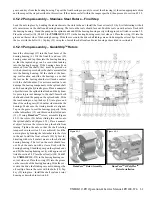
Страница 15: ...ditions Ver ify with UNIBLOC PUMP or the documentation supplied with the pump that the operating parameters are not exceeded Always rinse well with clean water after using cleaning agent 4 2 Steam In Place SIP The pump can be manually cleaned or cleaned with Steam In Place SIP Following is an example of suggested SIP procedure However specific advice for each application can be obtained from your ...

Страница 16: ...g kit Qty 1 5 o rings 1 wet end o ring kit for Metal Rotors Qty 1 5 o rings 4 4 Shaft Seal Service DISENGAGE POWER TO THE MOTOR before proceeding with the following steps If the pump is connected to piping depressurize the system and close valves on both the suction and discharge sides to isolate the pump from the rest of the system Disconnect the piping from the pump If service is to be performed...

Страница 17: ...tionary Seal Faces and Stationary Seal O Rings by pulling them out of the rotor housing Remove the Rotating Seal Faces the Rotating Seal O Rings and Rotating Seal Washers by sliding them off the shafts To avoid damage carefully handle and store the loose Stationary Seal Faces and the Rotating Seal Faces so that their lapped sealing surfaces do not get scratched 4 4 1 2 UNIBLOC PD 200 275 Single Me...

Страница 18: ...Rings with water or coat them with a lubricant that is acceptable for use with the product Slide the Rotating Seal O Rings onto the shafts and then the Rotating Seal Faces slotted sides first Align the slots in the Rotat ing Seal Faces with the pins in the Drive Collars Push the Rotating Seal Faces against the Drive Collars so that the Rotating Seal O Rings seat properly Place the Stationary Seal ...

Страница 19: ...Ink markings can be made on surface of Rotor Housing to show location of pins and similar markings can be made on seal face to show location of pin slots Align the Stationary Seal pin slots with the Seal Retaining Ring pins Evenly hand press the Stationary Seal Face until fully seated Stationary Seal Face will be fully seated once a spring compression can be felt Place the Rotating Seal O Ring on ...

Страница 20: ... the flush housings after all other seal parts have been removed back into the rotor housing seal bores Push or tap the lip seals with a tube to remove them 4 4 2 2 Flushed Single Mechanical Seal Installation Place the mating ring o rings 33a in the rotor housing seal bores Only lubricate these o rings with water or alcohol Push the mating rings into the rotor housing so that they seat flat with t...

Страница 21: ... from the Flush Housings Loosen the Drive Collar set screws by inserting an allen wrench into the flush housing port holes Loosen the stud nuts item 43 in Figure 4 4 1 Remove the rotor housing item 1 in Figure 4 4 1 by pulling on the ports or by tapping gently with a rubber mallet and lay it rotor cavity down so that the seals face up Do not rock the housing back and forth excessively or let it co...

Страница 22: ...tack the seal components on the Stationary Seal Faces primary Begin with Rotating Seal Faces primary slotted sides up Place the Rotating Seal O Rings primary into the Rotating Seal Faces primary Next place the Drive Collars into the the Rotating Seal Faces primary Making sure to align the slots with the pins push the Drive Collar gently to seat the o rings Place the Rotating Seal O Rings secondary...

Страница 23: ...es Truck Transport pumps 4 4 4 1 UNIBLOC 200 575 Double O Lip Seal Removal Loosen the stud nuts item 43 in Figure 4 4 1 Remove the rotor housing item 1 in Figure 4 4 1 by pulling on the ports or by tapping gently with a rubber mallet The entire seal with all components will come off attached to the rotor housing Remove the Bolts and Seal Retaining Rings Pull the Double O Lip Seal Cartridges out of...

Страница 24: ...501 551 576 Front Loaded Double O Lip Seal Installation Check the Wear Sleeves for wear If grooves are noticeable the sleeves may need to be replaced Place new Seal Cartridge O Rings into the groove of the Seal Cartridges Clean the rotor housing seal bores Apply product compatible lubricant to the bores and the shafts Slide the assembly sleeves onto the splined shaft ends These must be used to pre...

Страница 25: ...Studs by locking two M6 nuts against each other on the exposed threaded stud ends Remove the Rotor Housing by pulling on the ports or by tapping gently with a rubber mallet All seal parts will come off with the housing Remove the Seal Retaining Rings by unscrewing the Retaining Ring Bolts The Retaining Ring O Rings and Seal O Rings can now be removed 4 4 5 2 UNIBLOC 200 275 Single O Ring Seal Inst...

Страница 26: ...ional sleeve is used sleeve will be removed with cartridge 4 4 5 4 UNIBLOC 300 575 Single O Ring Seal Installation Check the shafts or optional sleeve for wear If grooves are noticeable they may have to be replaced Otherwise the Seal O Rings may not seal properly or may fail prematurely Place a new Retaining Ring O Ring into the groove of the Seal Re taining Ring Attach the Seal Retaining Ring to ...

Страница 27: ...ing system as discussed in section 3 3 disconnect it from the Flush Housings Loosen the stud nuts item 43 in Figure 4 4 1 Remove the Rotor Housing by pulling on the ports or by tapping gently with a rubber mallet All seal parts will come off with the housing Remove the Flush Housings by unscrewing the Bolts The Retaining Ring O Rings and Seal O Rings can now be removed 4 4 6 1 Double O Ring Seal I...

Страница 28: ...he rotors are metal slide the rotor shaft o rings 27 over the splined shaft ends and on the step if applicable One of the rotors will have a small marking on the rear end This indi cates that this rotors match with the drive shaft Slide the rotors over the corresponding shafts and push them making sure the o rings seat properly The rotors must make contact with the shafts Place o rings 26 on the r...

Страница 29: ...ve the correct values If the measured clearances at positions 9 and 11 are not within the tolerances listed the shafts must be adjusted by disassembling the gearbox as instructed in section 3 0 and changing the shims 11a Place the front cover 2 and the o ring 28 on the studs Tight en the front cover nuts 16 Check the oil level in the gearbox as described in section 5 2 The pump is now ready to be ...

Страница 30: ... a hydraulic press before the shafts are installed into the bearing housing Oil the shafts at the bearing seat location and slide the bearings on so that the text on the bearing shoulder will make contact with the shaft shoulder Use extreme caution to not damage the bearing components or the splined shaft end when using the hydraulic press Place a non metal object between the splined shaft end and...

Страница 31: ...d slide the bearings on so that the text on the bearing shoulder will make contact with the shaft shoulder Use extreme caution to not damage the bearing components or the splined shaft end when using the hydraulic press Place a nonmetal object between the splined shaft end and the hydrau lic press to prevent damage to the shaft Insert both shafts and stand the pump on the splined ends Slide the re...

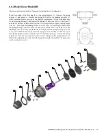
Страница 32: ... housing 10 to reveal the adjusting mechanism Release the lock ring 15 and turn it and the adjusting sleeve 16 clockwise until they bottom out Turn the sleeve counterclockwise until the pressure gauge begins to drop Lock this posi tion with the lock ring 15 Keep in mind that this pressure must be approximately 0 3 0 7 bar 5 10 psig lower than the desired relief pressure since the pump will continu...

Страница 33: ...8 will now be removable as one unit It is now possible to replace the diaphragm 9 10 Press back the diaphragm 9 10 on the cover 12 after replacement Slide the spring housing 5 back on the cover bolts 11 hold the stem 7 and disk 8 on the diaphragm 9 10 so they stay inside the housing Fasten the spring housing 5 to the cover 12 with the dome nuts 4 Place the spring 6 over the stem 7 Make sure you ha...

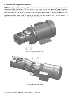
Страница 34: ...gure below It is important to always remove flange connected to electric or gear motor first to ensure limited loss of bearing housing oil These bolts would also need to be removed when rotating pump from horizontal to vertical port position or visa versa Once pump is decoupled from the electric or gear motor the Direct flange for CompacTM Direct or Flex flange for CompacTM Flex will act as the re...

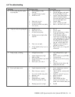
Страница 35: ...r closed valves or obstructions In crease pump speed BUT DO NOT EXCEED PRESSURE LIMITS OF PUMP Increase discharge pipe size Increase pump size 5 Tighten cover nuts to torques specified in section 5 3 6 Replace front cover o ring with correct size C Pump is noisy cavitating 1 Collapsed suction hose 2 Liquid temperature too high 3 Speed too high 4 Viscosity higher than Expectected 5 NPSHA too low 6 ...

Страница 36: ...ted 4 Motor pump misalignment 1 Increase motor size 2 Lower pump speed Lower pressure Check suction and discharge piping for closed valves or obstructions 3 Decrease pump speed Increase pipe size or shorten discharge pipe length 4 Correct alignment G Shaft seals leak 1 Loose drive collar on single mechanical seals 2 Worn parts 3 Seals have been operated without product in pump or with out flushing...

Страница 37: ...7 5 0 Technical Data 5 1 General Dimensions and Weights Drawing D100 shows overall dimensions for all models 200 0 to 677 A separate service manual is required for model 600 677 501 Series pumps are not shown in general dimensions below UNIBLOC PUMP ...

Страница 38: ...lubricated the pump must first be stopped Remove the oil level check plug If oil does not come out of this hole it must be added through the vent hole until it starts to do so Reattach the vent and oil plug and resume operation If filling bearing housing oil with rear cover removed fill oil level to approximately 1 8 from completely submerging the pump s timing gears Ensure oil has fully settled a...

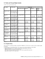
Страница 39: ...Hand tight Hand tight 3 Hand tight Hand tight Foot Pedestal Mounting Bolt 19 Key Size mm Torque Settings Nm Torque Setting lbft N A N A N A 6 Hand tight Hand tight 8 Hand tight Hand tight 8 Hand tight Hand tight Rotating Rotate Turn Shaft by turning rotors bolt 14a Socket Size mm Torque Settings Nm Torque Setting lbft 10 with part 6006 2 2 1 5 13 4 3 17 6 4 5 19 10 7 5 Shaft Guard Key Size mm Torq...

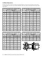
Страница 40: ... 4 3 1 12 14 4 7 5 5 6 8 2 4 3 1 250 12 14 4 7 5 5 6 8 2 4 3 1 12 14 4 7 5 5 6 8 2 4 3 1 275 14 16 5 5 6 3 6 8 2 4 3 1 12 14 4 7 5 5 6 8 2 4 3 1 300 15 17 5 9 6 7 12 14 4 7 5 5 12 14 4 7 5 5 8 10 3 1 3 9 350 17 19 6 7 7 5 16 18 6 3 7 1 12 14 4 7 5 5 8 10 3 1 3 9 400 20 22 7 9 8 7 20 22 7 9 8 7 14 16 5 5 6 3 8 10 3 1 3 9 450 22 24 8 7 9 4 20 22 7 9 8 7 14 16 5 5 6 3 8 10 3 1 3 9 500 501 26 28 10 2 ...

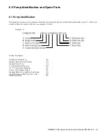
Страница 41: ...ption under section 1 2 Each serial number is linked to a unique build code see example 1 0 below Example 1 0 Product Description UNIBLOC PD 400 Size B Stainless Pump Bearing Housing A Standard Front Cover C 316 Stainless Rotor Housing D 1 5 T C Horizontal Mounting E Class C 316L Stainless Rotors F Standard Shafts Drive Shaft in Top Position G Single Mechanical Shaft Seal SiC vs SiC H EPDM Elastom...

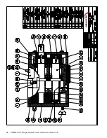
Страница 42: ...42 UNIBLOC PD Operation Service Manual PD200 576 UNIBLOC PUMP ...

Страница 43: ...UNIBLOC PD Operation Service Manual PD200 576 43 UNIBLOC PUMP ...

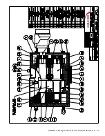
Страница 44: ...44 UNIBLOC PD Operation Service Manual PD200 576 UNIBLOC PUMP ...

Страница 45: ...UNIBLOC PD Operation Service Manual PD200 576 45 UNIBLOC PUMP ...

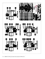
Страница 46: ...46 UNIBLOC PD Operation Service Manual PD200 576 UNIBLOC PUMP ...

Страница 47: ...UNIBLOC PD Operation Service Manual PD200 576 47 UNIBLOC PUMP ...

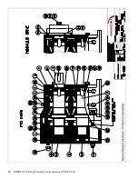
Страница 48: ...48 UNIBLOC PD Operation Service Manual PD200 576 UNIBLOC PUMP ...

Страница 49: ...UNIBLOC PD Operation Service Manual PD200 576 49 UNIBLOC PUMP ...

Страница 50: ...50 UNIBLOC PD Operation Service Manual PD200 576 3 ...

Страница 51: ......

Страница 52: ......

Страница 53: ...or instructed has been altered or used with unauthorized accessories has been subject to misuse abuse or accident or has been dam aged due to causes not related to poor workmanship or defective materials All parts or compo nents not manufactured by UNIBLOC PUMP are warranted only to the extent of the warranty of the respective manufacturers ALLIMPLIED WARRANTIES INCLUDING THE IMPLIED WARRANTIES OF...

Отзывы: