background image

USER MANUAL — 74-36103-ENG R6  

5

INTRODUCTION

This manual includes instructions and information that are necessary for a normal and secure use of the 

ook<cocoon>> 

bed, model FL36. Reading and understanding of instructions and information included in this 

manual, or other documents supplied with the product, are required prior to usage, or prior to perform maintenance 

on the equipment.

Product description

The 

ook<cocoon>>,

 model FL36, is an AC-powered medical bed with 4 built-in electric DC actuators. The height 

and surface contours are adjustable. The bed includes movable and latchable siderails or patient mobilization 

helper, and controls. The product offers a range of options and accessories outlined in the manuals, including but 

not limited to: 

bed exit system, fixed 

IV pole, patient helper, oxygen bottle holder and patient control. The expected 

life under normal usage and maintenance is 10 years.

Product intended use

The 

ook<cocoon>>, 

model FL36, is designed for use in the following environments: long term care establishments, 

recovery, therapeutic or rehabilitation areas. The product can be used for patient transportation between bays and 

procedural rooms. The overall capacity of the bed goes up to 500 lb/227 kg. The bed is designed for the use of 

one single person and, to be used with a sleep surface. The patient sleep surface can be 80" or 84" long.

Users are health care providers, bystanders, maintenance staff and the patient. Lockout of patient controls can 

limit patient access to functionalities. Only trained personnel or service technician should perform set up or 

maintenance on the bed.

Contact 

The manufacturer can be contacted for any assistance regarding the set up or the use of the bed, its maintenance 

or to report unexpected events at:

Umano Medical Inc.


230 boulevard Nilus-Leclerc, L’Islet QC G0R 2C0 CANADA 

T: (418) 247-3986 

T: (844) 409-4030 

[email protected]

Содержание ook cocoon

Страница 1: ...2 0 1 7 0 8 7 4 3 6 1 0 3 E N G R 6 User manual FL36...

Страница 2: ......

Страница 3: ...2 0 1 7 0 8 7 4 3 6 1 0 3 E N G R 6 User manual FL36...

Страница 4: ...rmission of the publisher except in the case of brief quotations embodied in critical reviews and certain other noncommercial uses permitted by copyright law For permission request write to the publis...

Страница 5: ...l 27 Accessory and equipment sockets 27 Power cord support brackets 27 CPR release optional 28 Bed exit system connectors optional 28 Auxiliary power outlets and USB port optional 29 Communication por...

Страница 6: ...ctions FA64509 70 Removable patient control 5 functions FA64510 71 PREVENTIVE MAINTENANCE 73 Preventive maintenance annual checklist 74 CLEANING 75 Cleaning 75 Disinfection 75 Mattress cleaning and ca...

Страница 7: ...ted life under normal usage and maintenance is 10 years Product intended use The ook cocoon model FL36 is designed for use in the following environments long term care establishments recovery therapeu...

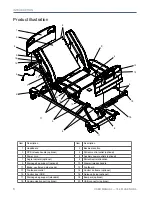
Страница 8: ...estraint location 9 Drainage bag support optional 10 Siderail release handle 11 Brake neutral and steer pedal 12 Footboard 13 Footboard control 14 Control on frame optional 15 Control box CB6 16 Nurse...

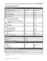
Страница 9: ...th 5 dual casters lowest with 5 dual casters 31 5 11 5 30 10 80 cm 29 2 cm 76 2 cm 25 4 cm Patient sleep surface width length 35 80 84 88 9 cm 203 2 cm 213 4 cm Under bed central zone clearance 5 12 7...

Страница 10: ...nts Electrical and mechanical requirements Comply with standards IEC60601 1 CAN CSA C22 2 60601 1 UL60601 1 IEC60601 1 2 IEC60601 2 52 CAN CSA C22 2 60601 2 52 Degree of protection IPX4 Degree of prot...

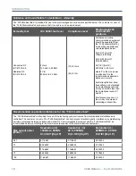
Страница 11: ...FL36 Medical Bed should ensure that it is use in such an environment Immunity test IEC 60601 test level Compliance level Electromagnetic environment guidance ESD IEC 61000 4 2 6kV Contact 8kV Air 6kV...

Страница 12: ...n meters Field strengths from fixed transmitters as determined by an electromagnetic site survey should be less than the compliance levels V1 and E1 Interference may occur in the vicinity of equipment...

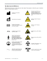
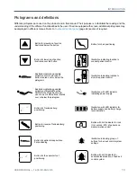
Страница 13: ...ates a fuse of 10 amperes 125 volts Indicates a terminal which is intended for connection to an external conductor for protection against electric shock in case of a fault or the terminal of protectiv...

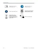
Страница 14: ...ory action Indicates that when disposed the equipment must be collected separately in accordance with the European Directive 2002 96 relatively to waste electrical and electronic equipment WEEE Indica...

Страница 15: ...ckrest section AND OR the Thigh Section per use of one or both buttons located over or below the pictogram Illustration indicating possible activation of Hi Lo per use of button located over or below...

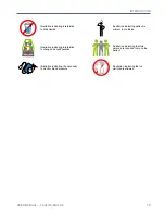
Страница 16: ...tress width Button for selection of audio signal type Illustration indicating necessity to monitor blood sugar level Illustration with LED indicators for active selection of tone Illustration indicati...

Страница 17: ...ration indicating patient is subject to confusion Illustration indicating interdiction to change bed configuration Illustration indicating the necessity to monitor blood pressure Illustration indicati...

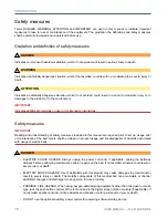
Страница 18: ...f safety measures included in this manual are required prior to set up usage and or maintenance of the bed Users shall be trained on product usage and knowledgeable of hazards associated with usage of...

Страница 19: ...If not avoided moderated to severe injuries and or permanent damages to bed or environment could occur Severe patient injuries could result of an improper usage of restraint straps Healthcare professi...

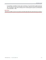
Страница 20: ...ronment could occur Always ensure of power cord proper condition prior to plug it into power outlet Always ensure that when routing cables from other equipment or hoists in the bed precautions are tak...

Страница 21: ...he equipments connected on the auxiliary power outlet are conforming to the electrical specifications like but not limited to power drawn leakage currents or electromagnetic compliance for electromedi...

Страница 22: ......

Страница 23: ...supply of 4 to 5 hours is needed to allow bed to reset its settings according to environmental conditions of use and to reach a minimum charge of the battery In case of complete discharge bed may need...

Страница 24: ...ful release the buttons b If amber LED lights are flashing and a single beep sounds this indicates that the procedure was not successful and should be redone Ensure the bed is completely flat and that...

Страница 25: ...ity screen will turn off completely and get in sleep mode If a screen saver is activated the information will be displayed while in sleep mode To get out of sleep mode press on screen or on screen but...

Страница 26: ...audible signal is emitted from the foot board or through the nurse call system it indicates that the bed exit system as detected a movement from the patient or that the patient as press the button of...

Страница 27: ...2 feet towards desired direction for the steering caster activation A click sound indicates that the caster is locked for steer motion Backrest section angle degree indicator optional An integrated an...

Страница 28: ...l Locations are available for patient restraint straps Four are located under the mattress surface two at head end of bed A and two at foot end of bed B The six mattress retainers can also accomodate...

Страница 29: ...will arm when patient is properly positionned in bed flashing amber bed exit has been triggered or motion interrupt has been triggered if applicable solid amber bed exit is in pause mode if applicable...

Страница 30: ...avoid injuries or product damages ensure total clearance around product prior to usage ATTENTION Usage shall be limited to emergency situations only An over usage could lead to mechanical degradation...

Страница 31: ...currents or electromagnetic compliance for electromedical systems IEC60601 1 2005 Ensure proper power supply and proper grounding reliability with the bed power cord connected to a hospital grade outl...

Страница 32: ...is removed lockouts of head or foot section motion lockouts of hi lo Trendelenburg and reverseTrendelenburg bed exit system activation deactivation battery charge level Do not use a sharp or small poi...

Страница 33: ...environment Do not use siderails to move the bed If not avoided situation could result in mechanical damages which could lead to patient fall Use headboard or footboard to move the bed ATTENTION Patie...

Страница 34: ...a click will be heard 2 Verify that patient mobilzation helper is properly locked by doing a head to feet movement Lower a patient mobilization helper 1 Grasp the upper center of the patient mobilizat...

Страница 35: ...ns and will be used as unique bed control The control can be stored out of reach of the patient on the support at head end of the bed with the hook on the back of the patient control A clip installed...

Страница 36: ...gaps wider and could result in increased risk of patient entrapment Refer to labeling on headboard if required Integrated pump holder optional An integrated pump holder is located on the plastic foot...

Страница 37: ...ED indicator constantly ON by the power cord pictogram indicates the bed is power supplied If bed operates on battery after 2 minutes of non motion the sleep mode will activate to save energy all LED...

Страница 38: ...The bed exit detection system must be used with patients with minimum weight of 50 lb 22 6 kg If not avoided the bed exit detection system may not detect all movements and the functionality could be a...

Страница 39: ...eactivate bed exit control or stop alarm signal press button for the selected level of detection for 2 seconds ensure LED indicator turns OFF The AUTO arm press button offers the possibility to automa...

Страница 40: ...embrane without display screen Refer to Bed exit configuration page 36 for details about their functions IMPORTANT Total lockout when activated through the display screen will not operate if bed is on...

Страница 41: ...AL 74 36103 ENG R6 39 Detailed screen functions SW 1 3 The following section details the screen functions for bed equipped with software version 1 3 The software version can be verified through Prefer...

Страница 42: ...bed or Auto arm is set it will turn green to indicate the bed exit control is activated If the patient is not in bed or Auto mode is not set the menu display will turn flashing orange in alarm If the...

Страница 43: ...hen activated and AUTO displays on Arm button Inform to set up a screen saver configured to inform caregivers with color coding and or different pictograms from Pictograms library and or siderail conf...

Страница 44: ...atures Entries related to bed exit control are highlighted in green to indicate activation and highlighted in orange to indicate an alarm Log displays the description date and time of the activity Sel...

Страница 45: ...n once one or more are activated The Inform pictogram also displays in the upper right corner of the display screen to inform caregivers that indicators related to patient s condition have been activa...

Страница 46: ...load cell values units selection calibration bed options and software version If PIN protected contact maintenance for access or refer to Maintenance Manual for instructions Date Time to set date and...

Страница 47: ...ws Minutes menu and navigate with UP DOWN arrows OK to set date and time and return to preference menu Lights screen optional Select Cancel to cancel command and return to preference menu Minus to dec...

Страница 48: ...Identification screen to label the equipment with a color code and text The label will display over the date and time in the Home screen A maximum of 20 digits can be entered as a text label Select C...

Страница 49: ...confirm selection and return to preference menu Brightness screen Select Cancel to cancel command and return to preference menu Minus to decrease screen brightness intensity Plus to increase screen br...

Страница 50: ......

Страница 51: ...AL 74 36103 ENG R6 49 Detailed screen functions SW 2 0 The following section details the screen functions for bed equipped with software version 2 0 The software version can be verified through Prefer...

Страница 52: ...eader will change to disarm Menu display if patient is in bed or Auto arm is set it will turn green to indicate the bed exit control is activated If the patient is not in bed or Auto mode is not set t...

Страница 53: ...the pause completely Resume to 5 min to reset the time to a total of 5 minutes Close to keep the remaining time the same and to return to the Home Screen When Auto Arm is activated and the pause finis...

Страница 54: ...m button turns green when activated and AUTO displays on Arm button Inform to set up a screen saver configured to inform caregivers with color coding and or different pictograms from Pictograms librar...

Страница 55: ...f features Entries related to bed exit control are highlighted in green to indicate activation and highlighted in orange to indicate an alarm Log displays the description date and time of the activity...

Страница 56: ...reen once one or more are activated The Inform pictogram also displays in the upper right corner of the display screen to inform caregivers that indicators related to patient s condition have been act...

Страница 57: ...e remaining time will appear on screen saver and Home screen Preference screen Select Tools pictogram Maintenance menu to access the errors log load cell values units selection calibration factory set...

Страница 58: ...with UP DOWN arrows OK to set date and time and return to preference menu Lights configuration screen optional Select Cancel to cancel command and return to preference menu Minus to decrease screen n...

Страница 59: ...Identification screen to label the equipment with a color code and text The label will display over the date and time in the Home screen A maximum of 20 digits can be entered as a text label Select C...

Страница 60: ...ce menu Cancel to cancel command and return to Preference screen menu Motion interrupt optional The motion interrupt system offers the possibility to interrupt a downward motion from the bed elevation...

Страница 61: ...before performing the zero CanceltoreturntothePatientriskmanagement screen Undo Zero to apply the previous zero performed A message box will appear to indicate the date of the last zero performed and...

Страница 62: ......

Страница 63: ...push bar if not avoided permanent damages to the product could occur Fully extended fixed IV pole length is 53 consider maximum bed height of 31 if transporting bed or if lighting or ceiling is low I...

Страница 64: ...vated Ensure proper clearance Installation 1 Remove screw from bottom of IV pole and from the IV pole storage support 2 Insert the folding IV pole in one of both corner bumpers of head end and insert...

Страница 65: ...bed or if lighting or ceiling is low IV pole will move with bed when elevation system activated Ensure proper clearance Installation 1 Remove screw from bottom of IV pole 2 Insert the fixed IV pole in...

Страница 66: ...31 if transporting bed or if lighting or ceiling is low IV pole will move with bed when elevation system activated Ensure proper clearance Installation 1 Remove screw from bottom of IV pole 2 Insert...

Страница 67: ...s recommended in order to prevent potential dammages to the walls Installation 1 Remove screw from bottom of IV pole and from the IV pole storage support 2 Insert the folding IV pole in the 1 left soc...

Страница 68: ...is recommended in order to prevent potential dammages to the walls Installation 1 Remove screw from bottom of IV pole and from the IV pole storage support 2 Insert the folding IV pole in 1 right sock...

Страница 69: ...3 is intended to be installed on the footboard to support pumps It has a maximum safe load capacity of 70 lb 31 kg ATTENTION Remove accessory when not in use Installation and removal 1 Insert or remov...

Страница 70: ...talled at the bed head end it has a maximum safe load capacity of 35 lb 16 kg Installation and operation 1 If applicable remove the retaining pin from bottom of support bar 2 Insert the support bar in...

Страница 71: ...llation 1 If applicable remove the retaining pin from bottom of the lower section 2 Insert the lower section roller bumper outside into one of both 1 1 2 sockets located at head end 3 Ensure it correc...

Страница 72: ...ged in the MJB junction box situated under the seat section 1 Using a flat blade screwdriver apply pressure upward to remove the connectors lock of the MJB Save for reuse 2 Using cutting pliers cut an...

Страница 73: ...id permanent damages WARNING Always ensure that patient is capable of proper usage of all functionalities offered on this control Always ensure that bed is clear of interference prior to any operation...

Страница 74: ......

Страница 75: ...hall perform preventive maintenance and servicing on this equipment If not avoided situation could result in electrical or electronic misconnection and lead to shock or fire hazards IMPORTANT Batterie...

Страница 76: ...Fasteners Labels Casters Ground chain Brake neutral and steer pedal Power cord Nightlight Actuators Battery Bumpers if applicable Mattress retainers Siderails mechanism Headboard and footboard CPR if...

Страница 77: ...the manufacturer instructions Cleaning Hand wash all surfaces with a soft cloth moistened with warm soapy water Avoid build up and over saturation of water or any cleaning solution Ensure that cleani...

Страница 78: ......

Страница 79: ...ging of the returned merchandise Modified or discontinued products not subject to return Limited warranty Umano Medical warrants to the original purchaser that the products shall be free from structur...

Страница 80: ...inage bag support 6 25 E EMC 9 F Footboard 6 30 34 37 Footboard control 6 23 35 38 Frame control 30 H Headboard 6 34 I IV pole 5 61 62 63 64 65 66 M Motion interrupt 58 Motion lockout 36 N Nightlight...

Страница 81: ...Umano Medical Inc 230 boulevard Nilus Leclerc L Islet QC G0R 2C0 CANADA 418 247 3986 844 409 4030 w w w u m a n o m e d i c a l c o m...

Отзывы: