background image

1


(1) Before Using 

1. Target Users 

Only persons who have used vacuum deposition equipment or trained based on this 
manual may operate this equipment. 

2. Read the Manual Thoroughly 

Please read this manual thoroughly in order to use the equipment in a safe and correct 
manner. 
Please pay particular attention when reading the section “To Safely Use This Equipment”. 

3. Keep This Manual in a Safe Place 

Keep this manual in a safe place. 
After reading this manual, be sure to keep it in a safe place where it is readily accessible 
to other users. 

4. Warranty 

(1) The warranty for this pump (this equipment) extends for a period of one year from the 

date of shipment. 

(2)  Any  malfunctions  or  defects  which  occur  under  normal  usage  conditions  during  the 

warranty period will be repaired free of charge. 

Note, the warranty stated here is an individual warranty covering the pump. In addition, 
the  scope  of  the  warranty  coverage  concerning  repairs  is  limited  to  the  repair  and/or 
replacement of parts. 
Normal usage conditions refer to the following: 

a) Ambient temperature and humidity during operation: 7 - 30°C, below 85% RH 
b) Operation in accordance with the user manual 

(3) Repair fees will incur during the warranty period for the following cases: 

a) Malfunctions due to a natural disaster or fire. 
b)  Malfunctions  caused  by  special  atmospheric  conditions,  such  as  salt  damage, 

inflammable gas, corrosive gas, radiation or pollution. 

c)  Malfunctions  caused  by  usage  conditions  that  differ  from  those  stated  in  the  user 

manual (performance specifications, maintenance and inspection, etc.). 

d)  Malfunctions  caused  by  modifications  or  repairs  carried  out  by  a  party  other  than 

the manufacturer, or by a service company not approved by the manufacturer. 

e) Malfunctions caused by noise (electric disturbance). 
f) Malfunctions that occur when not using a rated power supply. 
g) Malfunctions that occur when there is an abnormal rise in internal pressure due to 

the pump exhaust outlet being blocked during operation, etc. 

h) Malfunctions that occur, when the pump is damaged as a result of being dropped 

or falling, etc. 

i) Malfunctions which are determined by the manufacturer’s technical personnel to be 

caused by conditions that do not comply with the usage conditions for this vacuum 
pump. 

j) Malfunctions due to the replacement of consumables.         

(4) Disclaimer 

a) We shall not be liable for any malfunctions of our products caused by the customer, 

regardless  if  the  malfunction  does  not  fall  within  the  warranty  period,  nor  shall  we 
be liable for any loss of opportunity for the customer’s clients or for compensation 
for  any  damages  to  other  products,  labor  costs,  production  loss,  transportation 
expenses and other related work.   

b) We shall not be liable for any claims and patent infringements, including secondary 

damages, filed a claim by a third party against the customer. 


5. Statutory Requirements for Disposal 

Follow all statutory and local authority regulations when disposing of this equipment 
including used oil. 
Comply with regulations upon disposal.   

6. Safety during Repair 

When requesting repairs to this product, provide a full description of the conditions of use 
(particularly any use of dangerous materials) for the safety of repair personnel. 
In this case, fill in the Use Condition Check Sheet and attach to the product. 
If the use conditions are unknown, repair may be refused. 

Содержание VPC-061A

Страница 1: ...se read this manual thoroughly to ensure safe and effective operation of this equipment Keep this manual in a safe place Please note that due to performance upgrade the equipment described in this man...

Страница 2: ...andard Accessories 5 6 How to Use Switches Handles and Operation Levers 5 7 Layout of Switches Handles and Operation Levers 6 Evacuation system drawing Electrical system drawing 3 Opening the Package...

Страница 3: ...ce and Repair that Can be Made by User 14 3 Removal Maintenance and Installation of Devices 15 3 1 Oil sealed rotary vacuum pump 15 3 2 Oil diffusion pump 15 3 3 Oil mist trap 16 3 4 O ring at gas bel...

Страница 4: ...duced without permission of Ulvac Kiko Inc Read this section before using the VPC 061A Always follow the instructions below to safely use the device and prevent personal injuries from occurring The sy...

Страница 5: ...unding wire for 100 V power supply If you use a plug adapter connect the grounding wire with a nearest grounding terminal If incorrect grounding is made this may cause electrical shock in case of fail...

Страница 6: ...tion outlet of the oil sealed rotary vacuum pump during roughing operation Use an oil mist trap sold separately Otherwise oil spread may contaminate the room or affect human health Ventilate Pump is h...

Страница 7: ...iciency accident Caution Wear gloves When using liquid nitrogen wear gloves to protect your hands If liquid nitrogen splashes and adheres to your skin you may feel acute pain momentary Confirm complet...

Страница 8: ...ter of the oil diffusion pump 5 Cleaning of the inside of the base plate and the glass bell jar To make repair or maintenance other than the above contact us Replace periodically Oil mist trap sold se...

Страница 9: ...caused by modifications or repairs carried out by a party other than the manufacturer or by a service company not approved by the manufacturer e Malfunctions caused by noise electric disturbance f Ma...

Страница 10: ...materials other than evaporation materials and sample materials in the glass bell jar Reselling repairing and refurbishing of the product that are not permitted by us Avoid this action 2 Safety Device...

Страница 11: ...100 V 0 63 kVA Single phase 200 V 1 5 kVA External dimensions Main unit Weight Main unit Width 434 mm Depth 422 mm Height 673 mm Approx 32kg Finished color Rack Panel baking finish Munsell 6Y 8 0 8 b...

Страница 12: ...Model DPF 050 Evacuation speed 50 L sec Ultimate pressure 10 5 Pa Evacuation or VG 25 or equivalent suction opening 13 6 or equivalent Required power 0 25 kVA Oil for use SY 0 02L 1 set 5 Oil sealed...

Страница 13: ...firm Before handling switches handles or operation levers confirm the safety and conditions Name How to Operate MAIN switch Manual ON OFF AUTO switch Manual ON OFF ON lamp illumination MAIN P lamp Man...

Страница 14: ...6 7 Layout of Switches Handles and Operation Levers Evacuation system drawing Electrical system drawing...

Страница 15: ...here the following conditions are satisfied 1 Flat surface 2 Floor with sufficient strength 3 Well ventilated place 4 Place without direct sunlight 5 Room with temperatures between 7 C and 30 C 6 Loca...

Страница 16: ...Ground the grounding wire Employ Level D grounding The grounding wire for 200 V power supply is the green wire Use a plug with grounding wire for 100 V power supply If you use a plug adapter connect t...

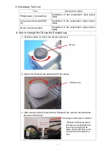
Страница 17: ...output power cable 6 How to change the Oil cap into Exhaust cap 1 Twist the black oil cap to the left and remove it Oil cap 2 Mount the Exhaust cap attached with the pump Exhaust cap 3 After changing...

Страница 18: ...quid nitrogen wear gloves to protect your hands If liquid nitrogen splashes and adheres to your skin you may feel acute pain momentary Confirm complete close After confirming complete closure of the m...

Страница 19: ...l in volume Approx 0 4 liters including vaporization volume upon fill in The liquid nitrogen lasts approx 4 hours when a volume of 0 4 liters is filled If all of the liquid nitrogen is vaporized the t...

Страница 20: ...nt OFF 2 Main valve COMPLETE CLOSE 3 Three way valve FORE Confirm 4 VENT V of Main Valve when necessary Open gradually 3 2 Vacuum evacuation of bell jar 1 VENT V of Main Valve CLOSE 2 Bell jar Install...

Страница 21: ...the shutter so as to remove them 9 Open the shutter and form the film on the material substrate 10 Run evaporation test 11 After film is formed close the shutter 12 POWER Lamp off OFF 13 Evaporation p...

Страница 22: ...rately should be replaced every six months to one year Clogging in the element increases evacuation resistance which may cause oil leakage from the axis sealing area or oil level gauge damage Work by...

Страница 23: ...fusion pump 1 Required tool 13mm Spanner x 1 2 Removal procedure All devices of the coater stop Confirm The primary power supply of the coater is removed Confirm Remove the Mate N Lock for the heater...

Страница 24: ...n Tighten with the O ring held 3 4 O ring at gas bell jar 1 Required tools None 2 Removal procedure Remove the O ring In this case do not cause any damage on the O ring groove 3 Order of attachment Ap...

Страница 25: ...f the ultimate pressure and the exhaust time is changed after an incorrect air intake If the ultimate pressure and the exhaust time is changed after long years of continuous use As necessary Cooling f...

Страница 26: ...ge the material Take longer evacuation time Failure in the oil sealed vacuum pump Refer to the Oil Sealed Vacuum Pump User s Manual Failure in measuring instrument Replace the measuring instrument The...

Страница 27: ...ring for hermetic sealing P 26 NBR 1 OK O ring for shutter N 8 NBR 1 OK Electrode pole gasket KV 1020 01 019 FPM 2 OK Main valve O ring for suction flange V 40 NBR 1 OK O ring for exhaust flange P 12...

Страница 28: ...flange V 24 NBR 1 OK Liquid nitrogen trap O ring for suction flange V 40 NBR 1 OK Specifications and quantity is different for special models 6 Disposal 1 Cautions upon Disposal Caution Comply with re...

Страница 29: ...der Secure the evaporation power Installable by user Filament Evaporation power Installable by user 140 material holder Fixing material Installable by user 8P Hermetic Terminals for energizing Install...

Отзывы: