Compressor Unit Instruction Manual
ULVAC CRYOGENICS INCORPORATED
3-3
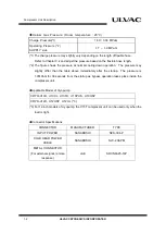
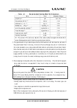
Table 3-1
Recommended Cooling Water for Compressor
Item
Unit
Allowable Range
pH (25°C)
※1
pH
6.5 - 8.0
Conductivity (25°C)
※1
mS/m
< 30
Chloride Ion, CI
-
※1
mg
/ L
< 50
Sulfate Ion, SO
4
2-
※1
mg SO
4
2-
/ L
< 50
Acid Consumption (pH4.8)
※1
mgCaCO
3
/ L
< 50
Total Hardness
※1
mgCaCO
3
/ L
< 50
Total Carbonic Acid
※1
mg/ L
< 10
Calcium Carbonate
mg/ L
< 75
※1
The values of the items are based on the water quality management standards of
Japan Refrigeration and Air Conditioning Industry Association.
(*) The ground water may contain large amount of total carbonic acid and lower the pH value. If
the ground water flows in one-way, corrosion of heat exchanger may occur in a short-term.
It is recommended to use cooling water with total carbonic acid density of lower than 10mg/L.
Since the dissolved ratio of total carbonic acid depends on the temperature and the pressure,
analyze the ground water immediately before exposing to the atmosphere. Check the water
supply whether it is from ground water or not before use. It is highly recommended to use
cooling tower to circulate the water containing a large amount of carbonic acid.
3. Stop supplying cooling water when the compressor is not running. If normal water supply is
done while the device is suspended, it may result in clog or corrosion of pipe and heat
exchanger.
Stop cooling water flow when the water temperature is below 10°C. If cooling water of
below 10°C keeps flowing while the compressor is not in operation, the compressor may
fail to startup due to increased viscosity of lubricating oil.
Cooling water must be drained from the compressor unit when:
・
Cooling water may freeze when the compressor unit is not running. The water pipe can
burst.
・
The compressor unit will be suspended for longer than a week.
・
Shipping the compressor unit.
Most of the cooling water can be drained by 30 seconds of blowing air with inlet pressure of
0.2MPaG and outlet opened to the air
CAUTION
Содержание C15T
Страница 2: ......
Страница 8: ...F 6 ULVAC CRYOGENICS INCORPORATED This page intentionally left blank...
Страница 14: ...S 4 ULVAC CRYOGENICS INCORPORATED This page intentionally left blank...
Страница 16: ...IW 2 ULVAC CRYOGENICS INCORPORATED This page intentionally left blank...
Страница 22: ...Compressor Unit Description 1 6 ULVAC CRYOGENICS INCORPORATED This page intentionally left blank...
Страница 34: ...Operation 4 2 ULVAC CRYOGENICS INCORPORATED This page intentionally left blank...
Страница 38: ...Disconnection and Storage 5 4 ULVAC CRYOGENICS INCORPORATED This page intentionally left blank...
Страница 46: ...Maintenance 6 8 ULVAC CRYOGENICS INCORPORATED This page intentionally left blank...
Страница 50: ...Troubleshooting A 4 ULVAC CRYOGENICS INCORPORATED This page intentionally left blank...
Страница 54: ...Circuit Diagram B 4 ULVAC CRYOGENICS INCORPORATED This page intentionally left blank...
Страница 57: ...Flexible Hose C 2 ULVAC CRYOGENICS INCORPORATED This page intentionally left blank...
Страница 61: ...CS 2 ULVAC CRYOGENICS INCORPORATED This page intentionally left blank...
Страница 63: ...Revisions R 2 ULVAC CRYOGENICS INCORPORATED This page intentionally left blank...


