background image


Disconnection and Storage 


5-2      


  ULVAC CRYOGENICS INCORPORATED


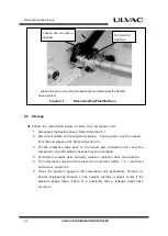
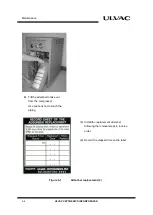
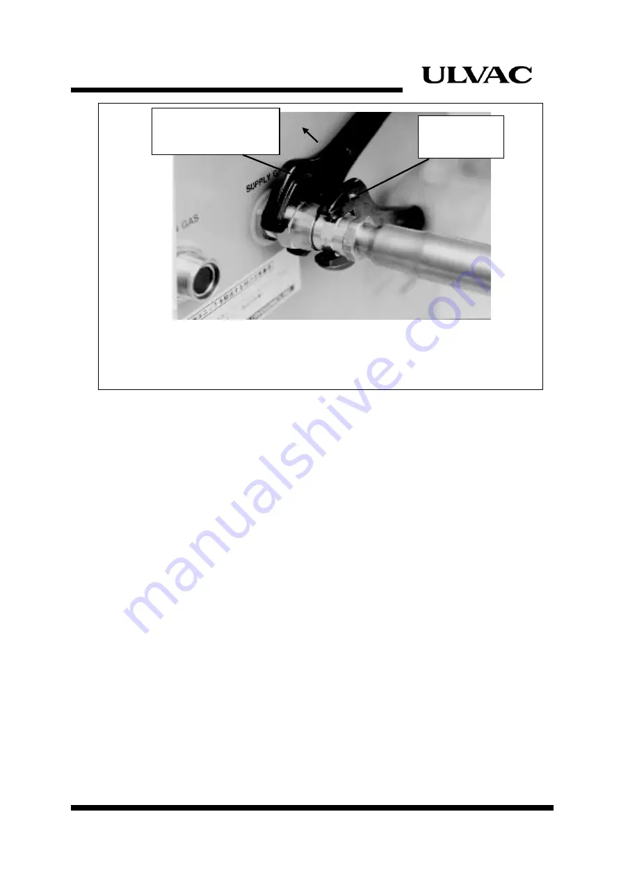
Loosen the union nut using two spanners and disconnect the flexible 

hose by hand. 

Figure 5-1 

Disconnecting Flexible Hose


5.2 

Storage 


  Follow the instructions below to store the compressor unit. 

1. 

Disconnect the flexible hoses. Refer to Section 5.1. 

2. 

Disconnect cables and cooling water piping.  Cooling water must be purged 

from the compressor unit. Refer to Section 3.3. 

3. 

Put the protective  caps back on the helium gas connectors and cover the 

compressor unit with plastic sheet as they were shipped. 

4. 

Avoid direct sunlight, heat, humidity, vibration, radiation, dust, wind and rain. 

5. 

The compressor unit should be placed on level floor (within 

±

5

°

) and  fixed 

not to move and/or fall. 

6. 

Check the pressure gauge of the compressor unit periodically.  Contact our


Service Engineering Division or the nearest customer support  center  if the 

pressure keeps lower. There is a possibility that a leakage might have 

occurred.   


Hold with a 

spanner. 


Loosen the nut with a 

spanner. 

Содержание C15T

Страница 1: ...port Trade Control Order which is based on international export control regimes Also when applying a refrigerator system to a cryocooler for optical sensors the cryocooler falls under row 10 2 of appe...

Страница 2: ......

Страница 3: ...where our product is used The personnel are also required to have specialized knowledge skills and qualification on the electricity the machinery the cargo handling and the vacuum Especially the perso...

Страница 4: ...wns resulting from using the product outside the specified specifications of the product Breakdowns due to contamination or corrosion caused by user s use conditions Breakdowns due to natural disaster...

Страница 5: ...splay Serial No Option Part Model Optional Part Serial No 4 Notes for repair and maintenance requests We may decline your request for the repair or the maintenance of our products if you refuse to giv...

Страница 6: ...fer this instruction manual or any of its parts to a third person without written permission from ULVAC CRYOGENICS 2 Information in this document might be revised without a previous notice for the spe...

Страница 7: ...ould result in severe injury or loss of life A caution describes safety hazards or unsafe practices which could result in personal injury or equipment damage Toxic gas or chemicals used There is a ris...

Страница 8: ...F 6 ULVAC CRYOGENICS INCORPORATED This page intentionally left blank...

Страница 9: ...1 3 2 Connecting Cooling Water Piping 3 2 3 3 Cooling Water 3 2 3 4 Connecting the Compressor Unit to the Cryopump 3 5 3 5 Connecting Electrical Cables 3 7 4 OPERATION 4 1 4 1 Before Operation 4 1 4 2...

Страница 10: ...e 3 6 Figure 3 4 Static Pressure and Temperature 3 7 Figure 3 5 Compressor Installation 3 8 Figure 5 1 Disconnecting Flexible Hose 5 2 Figure 6 1 Adsorber replacement 6 3 Figure B 2 C15T Wiring Diagra...

Страница 11: ...mination refer to the Maintenance section and follow the instruction The equipments regulators charging hoses adopters etc that can be used at the pressure of 2 0MPaG or higher are required to perform...

Страница 12: ...ur local dealership or Ulvac Techno Ltd to have it picked up or send it directory to our Service Engineering Division We only accept CTI adsorbers and our adsorbers Power supply voltage must be kept w...

Страница 13: ...or compressor units Please refer to Section 3 Table 3 1 Recommended Cooling Water for Compressor The upper limit of the compressor operating ambient temperature is 38 C Do not use the compressor in un...

Страница 14: ...S 4 ULVAC CRYOGENICS INCORPORATED This page intentionally left blank...

Страница 15: ...sorber coupling such as our charging adaptor for cryocooler maintenance 2 Remove the coupling to make it visible that the adsorber has been depressurized before proceeding to the next step Disposal Co...

Страница 16: ...IW 2 ULVAC CRYOGENICS INCORPORATED This page intentionally left blank...

Страница 17: ...ions Model C15T Power Source Voltage x Phase x Frequency 190 220VAC x 3 x 50Hz 200 230VAC x 3 x 60Hz Power in normal operation 1 3 3kW 4 1kW 50Hz 60Hz Cooling Type Water cooled Cooling Water Requireme...

Страница 18: ...n operation The pressure may slightly differ than the table above immediately after the startup The pressure is 1 7MPaG for 30 seconds from the startup as bypass operation takes place inside the compr...

Страница 19: ...SIDE REAR Figure 1 1 Dimensions Model START STOP E T M C15T SERIAL No No MADE IN JAPAN MODEL COMPRESSOR UNIT Tel 0467 85 0303 64 601 665 339 580 57 96 76 55 CAUTION INPUT POWER Disconnect the INPUT P...

Страница 20: ...bleshooting procedures SUPPLY RETURN Rc3 8 Rc3 8 Charging valve and fitting are on the back of the front panel Control Panel Elapsed Time Meter Helium Charge Valve Operation Start Cooling Water Inlet...

Страница 21: ...ove the control panel on the rear to operate switches on the side of the controller Figure 1 3 Major Components Controller CP1 CP2 FUSE1 1A FUSE2 1A Remote Local switch Coldhead Connector Power Connec...

Страница 22: ...Compressor Unit Description 1 6 ULVAC CRYOGENICS INCORPORATED This page intentionally left blank...

Страница 23: ...ng List Item Quantity Compressor Unit 1 Instruction Manual This book 1 Fuse 250V 1A 1 Metal Connector External signal Remote 1 Table 2 2 Optional Parts Item Quantity Input Power Cable 5 5mm2 x 4cores...

Страница 24: ...to the flexible hose Prevent twisting at the connection Refer to Appendix C for more information on handling of the flexible hoses Inspect the exterior of the flexible hose for twists or tear When th...

Страница 25: ...onnecting Electrical Cables 3 7 3 1 Installation 1 Place the compressor unit on a level floor within 5 2 The compressor unit must be operated in proper room temperature 10 C 38 C Avoid dust and moist...

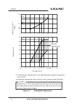
Страница 26: ...ons for leaks 3 3 Cooling Water 1 Determine the cooling water flow rate within the allowable range as shown in Fig 3 2 Always use the proper cooling water that meets the requirement Keep the cooling w...

Страница 27: ...ressure analyze the ground water immediately before exposing to the atmosphere Check the water supply whether it is from ground water or not before use It is highly recommended to use cooling tower to...

Страница 28: ...heat exchanger Figure 3 2 Cooling Water Requirement A dashed arrow in the above graph shows the water flow rate and pressure P required when the water temperature is 30 C Water flow rate is 4 5L min...

Страница 29: ...compressor unit to the cryopump See Figure 3 4 a Connect the helium gas supply flexible hose labeled SUPPLY to the helium gas supply connector on the compressor Then connect the other end of the hose...

Страница 30: ...rt straight and tighten by hand Tighten the self sealing coupling using two wrenches until the fittings are firmly sealed When using torque wrench torque the connection to 20N m Figure 3 4 Connecting...

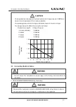
Страница 31: ...WARNING 1 Make the REMOTE RESPONSE wiring if necessary Do not operate the compressor with excess helium static charge pressure 1 65MPaG or above at room temperature 20 C to improve reliability The op...

Страница 32: ...om the compressor to the cryopump 3 Connect the ground 4 Connect the connector side of the input power cable to the compressor Connect the other side of the input power cable to the power source Note...

Страница 33: ...may be reversed Change any one set of RST phases 3 REMOTE LOCAL switch is properly set 4 Connectors are fixed firmly 5 Cooling water meets the requirements 6 Helium gas static pressure is within the a...

Страница 34: ...Operation 4 2 ULVAC CRYOGENICS INCORPORATED This page intentionally left blank...

Страница 35: ...mpressor unit 2 After the Super Trap and or cryopump refrigerator unit has been warmed up to room temperature disconnect the flexible hoses If flexible hoses are disconnected while the cryocooler is s...

Страница 36: ...Refer to Section 3 3 3 Put the protective caps back on the helium gas connectors and cover the compressor unit with plastic sheet as they were shipped 4 Avoid direct sunlight heat humidity vibration r...

Страница 37: ...the instructions below in addition to the above Operate the compressor unit for about an hour every three months to circulate lubricating oil to prevent the damage caused by the lack of the oil when s...

Страница 38: ...Disconnection and Storage 5 4 ULVAC CRYOGENICS INCORPORATED This page intentionally left blank...

Страница 39: ...ompressor is the replacement of the adsorber within every 30 000 hours Use more than 30 000 hours cause to be a machine trouble on refrigerator unit Keep to remove and replace the adsorber proceed wit...

Страница 40: ...ber 1 Remove the dust caps from the self sealing coupling halves at each end of the replacement adsorber 2 Install the replacement adsorber following the steps for adsorber removal in reverse order 3...

Страница 41: ...NCORPORATED 6 3 Figure 6 1 1 Adsorber replacement 1 Remove the jam nuts Loosen the seven bolts to remove the rear panel 2 Disconnect flexible hose from the adsorber inlet 3 Remove the adsorber mountin...

Страница 42: ...ED Figure 6 1 Adsorber replacement 2 5 Install the replacement adsorber following the removal steps in reverse order 6 Record the elapsed time on the label Tilt the adsorber to take out from the compr...

Страница 43: ...e the regulator which shows the range of 4 6 MPaG as outlet pressure The gas charge inlet of the compressor unit is 1 4B male flare Use helium gas with purity of 99 999 or above Follow the steps below...

Страница 44: ...ulator at 1 8 MPaG 5 Open the charge valve slowly and follow the instruction below based on the state of the compressor a If the compressor unit is running under normal operating conditions replenish...

Страница 45: ...ULVAC CRYOGENICS INCORPORATED 6 7 Figure 6 2 Charging Helium Gas Bottle Valve Regulator Charging Hose Remove the front panel He Charging Valve CRYO U Helium Gas Bottle Flexible Hoses Compressor High...

Страница 46: ...Maintenance 6 8 ULVAC CRYOGENICS INCORPORATED This page intentionally left blank...

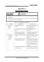
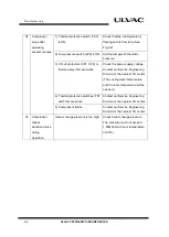
Страница 47: ...s connected properly 2 Circuit protectors CP1 CP2 are OFF Set circuit protector to ON See Fig 1 3 3 Phase reverse relay PRR is active STOP lamp lights off Interchange 2 phases of primary power Refer t...

Страница 48: ...the power supply voltage Contact our Service Engineering Division or the nearest CS center The cooling water temperature and the room temperature will be needed 4 Thermal protective switches TS1 and...

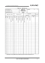
Страница 49: ...SSOR S N REFRIGERATOR S N Measuring condition Compressor unit Cryopump Remarks Temperature Pressure Date Time Measurer Room temp Humidity ETM High pressure helium gas MPaG Current Cooling water flow r...

Страница 50: ...Troubleshooting A 4 ULVAC CRYOGENICS INCORPORATED This page intentionally left blank...

Страница 51: ...in the refrigerator circuitry is shorted Rated current 1A PRR Reverse phase protective relay This relay does not allow the compressor to start when the compressor power wires are connected reverse ph...

Страница 52: ...spended while being connected to the power supply this switch lights ORANGE PB2 PL2 START push button switch Momentary Press to turn on the compressor unit The STOP switch turns off and the START swit...

Страница 53: ...ICATIONS Maximum voltage AC250V DC125V Maximum current 5A 5A Rated load Resistance load Induction load AC220V 5A 2A DC 24V 5A 2A Minimum applicable load DC5V 1mA CR2 Solenoid valve SOL relay This rela...

Страница 54: ...Circuit Diagram B 4 ULVAC CRYOGENICS INCORPORATED This page intentionally left blank...

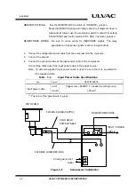
Страница 55: ...1 F2 2 CP2 3 CP2 5 CP2 4 CP2 6 SOL 1 2 CN4 1 CN4 2 CR4 4 4 4 12 CR4 4 CR4 12 CR2 8 2 8 CR2 2 12 CR2 12 CR4 14 4 14 CR4 4 13 CR4 13 ETM LPS PB1 PL1 PB2 PL2 FUSE1 2 CR4 OL TS1 TS2 TS3 Power connector C...

Страница 56: ...r Connecting 20N m Tighten until the self sealing coupling stops turning Connection 1 2B self sealing coupling 2 Handling Precautions When carrying a flexible hose hold the braid support of the hose B...

Страница 57: ...Flexible Hose C 2 ULVAC CRYOGENICS INCORPORATED This page intentionally left blank...

Страница 58: ...ut from the compressor and cooled down at an oil heat exchanger before being injected back into the compressor through an oil injection filter High temperature high pressure helium gas comes out from...

Страница 59: ...ef valve Injection Oil return Oil return relief valve exchanger filter gauge Helium heat orifice Oil orifice filter Differential pressure Oil heat Oil injection Solenoid controlled Valve 1 Suction fil...

Страница 60: ...6397 0112 Fax 81 6 6397 0126 Inquiries about cryostats or LN2 generators Kyoto Factory 140 1 Megawa Makishima cho Uji kyoto 611 0041 Japan T e l 81 774 28 5595 Fax 81 774 20 2201 ULVAC CRYOGENICS KORE...

Страница 61: ...CS 2 ULVAC CRYOGENICS INCORPORATED This page intentionally left blank...

Страница 62: ...Unit Instruction Manual ULVAC CRYOGENICS INCORPORATED R 1 Revision History Date Revision No Contents 2020 01 16 2020 09 29 2020 01 2020SR01 First edition Appendix B P B 5 B 6 Circuit Diagram has been...

Страница 63: ...Revisions R 2 ULVAC CRYOGENICS INCORPORATED This page intentionally left blank...

Отзывы: