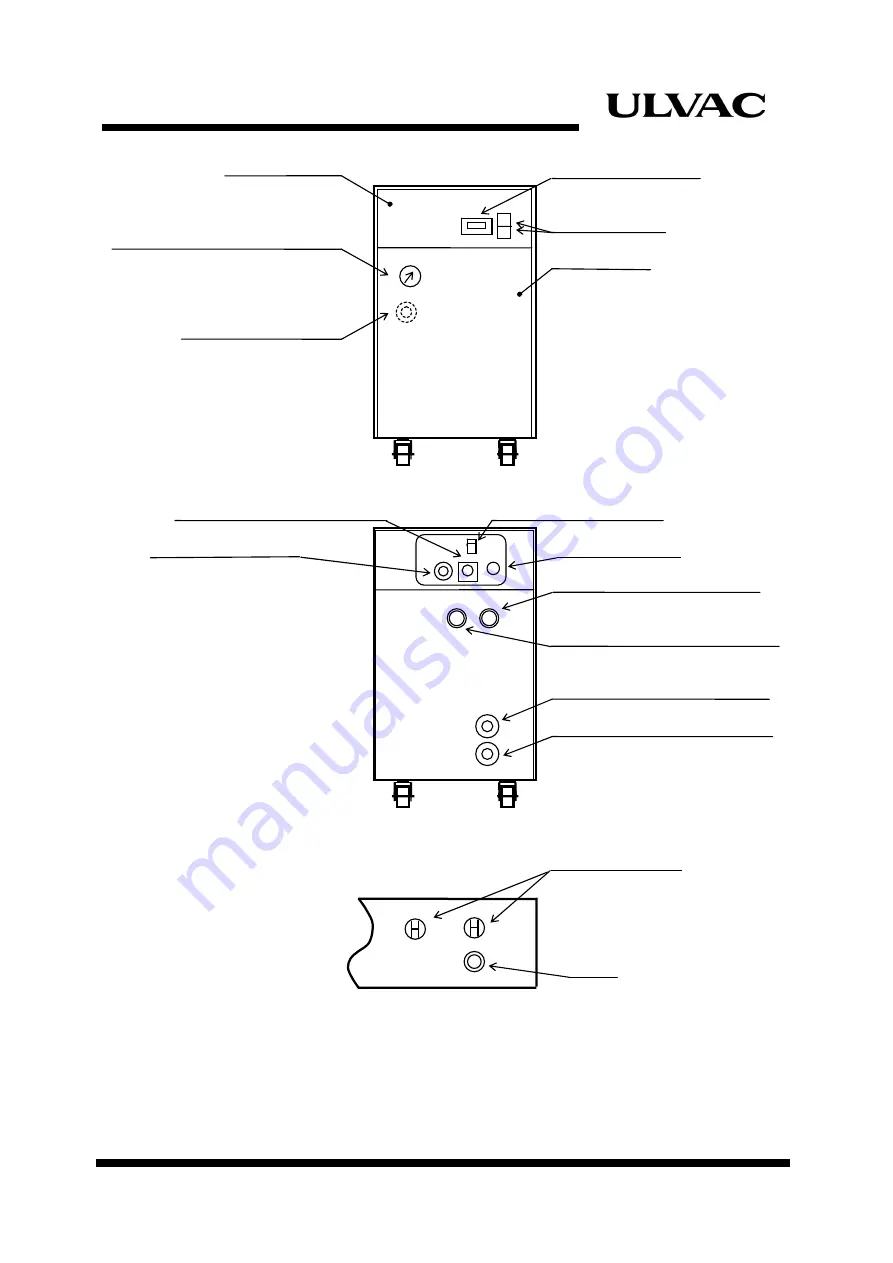
Compressor Unit Description
1-4
ULVAC CRYOGENICS INCORPORATED
【
FRONT
】
【
REAR
】
【
CONTROLLER (REAR)
】
*
For the operation of a controller switch, remove the control panel on
the rear of the compressor unit.
Figure 1-2
Major Components
Control Panel
Elapsed Time Meter
Helium Supply Pressure Gauge
ON/OFF Switch
Helium Charge Valve
(Fitting)
Front Panel
REMOTE/RESPONSE Connector
Cold Head Connector
REMOTE/LOCAL Switch
Power Connector
Helium Gas Supply Connector
Helium Gas Return Connector
Cooling Water Inlet (Rc3/8)
Cooling Water Outlet (Rc3/8)
Circuit Protector
Fuse
CP1
CP2
FUSE(1A)
Charging valve and
fitting are on the other
side of the front panel.
Содержание C10T
Страница 2: ......
Страница 8: ...F 6 ULVAC CRYOGENICS INCORPORATED This page intentionally left blank ...
Страница 14: ...S 4 ULVAC CRYOGENICS INCORPORATED This page intentionally left blank ...
Страница 16: ...IW 2 ULVAC CRYOGENICS INCORPORATED This page intentionally left blank ...
Страница 32: ...Operation 4 2 ULVAC CRYOGENICS INCORPORATED This page intentionally left blank ...
Страница 36: ...Disconnection and Storage 5 4 ULVAC CRYOGENICS INCORPORATED This page intentionally left blank ...
Страница 44: ...Troubleshooting A 4 ULVAC CRYOGENICS INCORPORATED This page intentionally left blank ...
Страница 47: ...Compressor Unit Instruction Manual ULVAC CRYOGENICS INCORPORATED B 3 B 4 ...
Страница 48: ...Compressor Unit Instruction Manual ULVAC CRYOGENICS INCORPORATED B 5 B 6 ...
Страница 50: ...Flexible Hose C 2 ULVAC CRYOGENICS INCORPORATED This page intentionally left blank ...
Страница 54: ...CS 2 ULVAC CRYOGENICS INCORPORATED This page intentionally left blank ...
Страница 56: ...This page intentionally left blank R 2 ULVAC CRYOGENICS INCORPORATED ...


