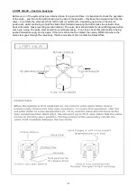
- 18 -
Appendix 1:
Parameter listing for Temperature Controller (For commissioning Engineers use only)
1
/
16
DIN PROCESS CONTROLLERS
CONCISE PRODUCT MANUAL
CAUTION:
Installation should be only performed by technically
competent personnel. Local Regulations regarding electrical
installation & safety must be observed.
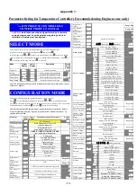
SELECT MODE
Select mode is used to access the configuration and operation menu functions.
It can be accessed at any time by holding down
and pressing
.
In select mode, press
or
to choose the required mode, press
to enter. An unlock
code is required to prevent unauthorised entry to Configuration & Setup modes. Press
or
to enter the unlock code, then press
to proceed.
Mode Upper
Display
Lower
Display
Description
Default
Unlock
Codes
Operator
Normal operation
None
Set Up
Tailor settings to the application
Configuration
Configure the instrument for use
Product Info
Check manufacturing information
None
Auto-Tuning
Invoke Pre-Tune or Self-Tune
Note: The instrument will always return automatically to Operator mode if there is no key
activity for 2 minutes.
CONFIGURATION MODE
First select Configuration mode from Select mode
(refer to section 2).
Press
to scroll through the parameters, then press
or
to set the required value.
Press
to accept the change, otherwise parameter will revert to previous value. To exit from
Configuration mode, hold down
and press
to return to Select mode.
Note: Parameters displayed depends on how instrument has been configured. Refer to
user guide (available from your supplier) for further details. Parameters marked * are
repeated in Setup Mode.
Parameter Lower
Display
Upper
Display
Adjustment range & Description
Default
Value
Input Range/Type
PT100 sensor
Scale Range Upper
Limit
Scale Range Lower Limit +100
to Range Maximum
100
Scale Range Lower
Limit
Range Minimum to
Scale Range Upper Limit -100
0
Decimal point
position
0=
XXXX,
1=
XXX.X,
2=
XX.XX,
3=
X.XXX
(non-temperature ranges only)
1
Control Type
Primary only
Primary & Secondary
(e.g. heat & cool)
Primary Output
Control Action
Reverse Acting
Direct Acting
Alarm 1Type
Process High Alarm
Process Low Alarm
Deviation Alarm
Band Alarm
No alarm
High Alarm 1
value*
Range Minimum to Range Maximum in display
units
Range Max
Low Alarm 1
value*
Range Min
Band Alarm 1
value*
1 LSD to span from setpoint in display units
Dev. Alarm 1
value*
+/- Span from setpoint in display units
Alarm 1
Hysteresis*
1 LSD to full span in display units
Alarm 2 Type*
Options as for alarm 1
High Alarm 2
value*
Range Max
Low Alarm 2
value*
Range Min
Band Alarm 2
value*
Dev. Alarm 2
Value*
Options as for alarm 1
Alarm 2
Hysteresis*
Loop Alarm
(disabled) or
(enabled)
Loop Alarm Time*
1 sec to 99 mins. 59secs
.
Alarm Inhibit
No alarms Inhibited
Alarm 1 inhibited
Alarm 2 inhibited
Alarm 1 and alarm 2 inhibited
Output 1 Usage
Primary Power
Secondary Power
Alarm 1, Direct
Alarm 1, Reverse
Alarm 2, Direct
Alarm 2, Reverse
Loop Alarm, Direct
Loop Alarm, Reverse
Logical Alarm 1 OR 2, Direct
Logical Alarm 1 OR 2, Reverse
Logical Alarm 1 AND 2, Direct
Logical Alarm 1 AND 2, Reverse
Retransmit SP Output
Retransmit PV Output
Linear Output 1
Range
0 to 5 V DC output
0 to 10 V DC output
2 to 10 V DC output
0 to 20 mA DC output
4 to 20 mA DC output
Retransmit Output
1 Scale maximum
-1999 to 9999
(display value at which output
will be maximum)
Range max
Retransmit Output
1 Scale minimum
-1999 to 9999
(display value at which output
will be minimum)
Range min
Output 2 Usage
As for output 1
Sec or Al2
Linear Output 2
Range
As for output 1
Retransmit Output
2 Scale maximum
-1999 to 9999
(display value at which output
will be maximum)
Range max
Retransmit Output
2 Scale minimum
-1999 to 9999
(display value at which output
will be minimum)
Range min
Output 3 Usage
As for output 1
Linear Output 3
Range
As for output 1
Retransmit Output
3 Scale maximum
-1999 to 9999
(display value at which output
will be maximum)
Range max
Display Strategy
,
,
,
,
or
(refer to section 8)
Serial
Communications
Protocol
ASCII
Mm
Mm
Modbus with no parity
Mm
Modbus with Even Parity
Mm
Modbus with Odd Parity
Serial
Communications
Bit Rate
.
1.2 kbps
.
.
2.4 kbps
.
4.8 kbps
.
9.6 kbps
.
19.2 kbps
Comms Address
1 to 255 (Modbus), 1 to 99 (ASCII)
Comms Write
Ww
Read/Write
Ww
Read only
Digital Input 1
Usage
Setpoint 1 / Setpoint 2 select*
Automatic / Manual select
Digital Input 2
Setpoint 1 / Setpoint 2 select*
Содержание UKE-8-50
Страница 3: ... 3 ...
Страница 9: ... 9 ...
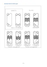
Страница 13: ... 13 Examples of Gasket and Plate types ...

