background image


__________________________________________________________________________________ 

DESMI Pumping Technology A/S 


Tagholm 1 

9400 Nørresundby 

 Denmark 

Tel: +45 96 32 81 11 Fax: +45 98 17 54 99 
E-mail: 

[email protected]


www.desmi.com


OPERATION AND MAINTENANCE INSTRUCTIONS 


DESMI end suction centrifugal pump 


NSLH and NSLV Spacer 


DESMI Pumping Technology A/S 

Tagholm 1 

– DK-9400 Nørresundby – Denmark 


      Tel.:   +45 96 32 81 11 

Fax:   +45 98 17 54 99 

E-mail: 

[email protected]


      Internet: 

www.desmi.com


Manual: 

T1529 


Language: 

English 


Revision: 

J(07/22) 


Special pump No. .................  


Содержание NSLH

Страница 1: ...1 Fax 45 98 17 54 99 E mail desmi desmi com www desmi com OPERATION AND MAINTENANCE INSTRUCTIONS DESMI end suction centrifugal pump NSLH and NSLV Spacer DESMI Pumping Technology A S Tagholm 1 DK 9400 Nørresundby Denmark Tel 45 96 32 81 11 Fax 45 98 17 54 99 E mail desmi desmi com Internet www desmi com Manual T1529 Language English Revision J 07 22 Special pump No ...

Страница 2: ...5 3 DISMANTLING SEAT 7 5 4 DISMANTLING SHAFT WITH BEARINGS 7 5 5 INSPECTION 7 6 ASSEMBLING 7 6 1 FITTING SEALING RINGS 7 6 2 FITTING SHAFT WITH BEARINGS 7 6 3 FITTING WATER DEFLECTOR 8 6 4 FITTING SHAFT SEAL 8 6 5 FITTING IMPELLER 8 6 6 FITTING BEARING HOUSING AND SHAFT SEAL COVER 8 6 7 SHAFT 8 6 8 FITTING COUPLING 9 7 FROST PROTECTION 10 8 DISMANTLING 10 9 START UP 10 9 1 STARTING 10 10 SYSTEM BA...

Страница 3: ...SPARE PARTS LIST 100 265 WITH INDUCER 22 19 ASSEMBLY DRAWING AND SPARE PARTS LIST Ø 330 415 465 23 20 ASSEMBLY DRAWING AND SPARE PARTS LIST 100 330 100 415 AND 100 465 WITH INDUCER 24 21 ASSEMBLY DRAWING AND SPARE PARTS LIST 125 330 WITH INDUCER 25 22 ASSEMBLY DRAWING AND SPARE PARTS LIST Ø 525 26 23 ASSEMBLY DRAWING AND SPARE PARTS LIST 300 418 27 24 ASSEMBLY DRAWING AND SPARE PARTS LIST 350 525 ...

Страница 4: ...ns are divided into two parts covering the groups ø215 265 and ø330 415 465 525 as the designs of these two groups are different The numbers refer to the standard impeller diameter of the pump E g ø215 265 Pumps with ø215 or ø265 impellers The back of the impeller is equipped with relief blades to reduce the load on the bearings ø330 415 465 525 Pumps with ø330 ø415 ø465 or ø525 impellers The back...

Страница 5: ...t bearing housing 14 Spacer heavy bearing housing 15 Spacer heavy bearing housing and heavy motor bracket special motor bracket 16 Compact spacer Z may be the following i PN16 flanges j PN25 flanges k Special flange l Other shaft seal m BS flanges n ANSI flanges o Shockproof design p Other design q JIS flanges r With inducer Any use of the pump is to be evaluated on the basis of the materials used...

Страница 6: ... be increased by factor 1 5 Pump size Fy N Fz N Fx N F My Nm Mz Nm Mx Nm Mt 65 215 65 265 650 840 750 1340 510 310 380 700 80 215 80 265 80 330 800 950 850 1500 550 350 400 750 100 215 100 265 100 330 100 415 100 465 1000 1250 1150 2000 650 400 500 900 125 215 125 265 125 330 125 415 1250 1600 1430 2500 830 520 650 1160 150 265 150 330 150 415 150 465 1500 1900 1700 2950 1000 650 800 1400 200 265 ...

Страница 7: ...ated figure multiplied by 1 4 3 INSTALLATION See also DESMI Guidelines for pump installations at www desmi com media sd5ltlox guidelines_uk pdf 3 1 MOUNTING FASTENING The pump should be mounted and fastened on a solid base plate with a flat and horizontal surface to avoid distortion The max permissible loads on the flanges stated in paragraph 2 2 are to be observed At installations pumping hot or ...

Страница 8: ...D combination Pump size Weight in kg A D combination 65 215 150 155 150 415 420 455 65 265 195 200 150 465 498 80 330 295 310 150 265 256 277 80 215 160 170 200 330 432 473 80 265 212 224 200 415 548 592 100 330 317 335 200 525 885 950 100 415 354 366 200 265 323 327 100 465 367 374 250 330 490 537 100 215 165 175 250 415 602 657 100 265 223 238 250 525 930 1004 125 330 320 345 300 415 690 758 125...

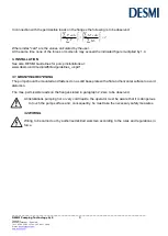
Страница 9: ... pull downwards take out the spacer 72 Loosen the pointed screw 73 and pull the coupling part pump 70 off the shaft Dismantle the copper pipe 58 Remove Allen screws 22 which hold the shaft seal cover 20 to the pump casing Remove the shaft seal cover from the pump casing by means of the pointed screws 86 The bearing housing with shaft and impeller can now be lifted up from the pump as a unit and th...

Страница 10: ...om behind the shaft seal cover 5 4 DISMANTLING SHAFT WITH BEARINGS Before dismantling the shaft with bearings remove the sunk key 16 The shaft can now be pulled out of the bearing housing allowing inspection of the bearings 5 5 INSPECTION When the pump has been dismantled check the following parts for wear and damage Sealing rings impeller Max clearance 0 4 0 5 mm measured in radius Shaft seal sha...

Страница 11: ...ended to avoid that the rubber bellows is cut Push the slide ring over the shaft with the hand If the rubber bellows is tight use a fitting tool and take care that the slide ring is not damaged If the carbon ring is not fixed it is important to check that it is fitted correctly i e the chamfered lapped side is to face the seat The carbon ring can be held by a little grease When using silicone grea...

Страница 12: ...o the actual coupling size which appears from the coupling element itself Fit the flexible coupling to the coupling part pump by means of the Allen screws 76 which are to be greased a little under the bolt head and tightened with the torque stated Thread Torque Coupling element Distance M8 25 Nm V1700 0832 4 mm M10 50 Nm V1700 1042 4 mm M12 90 Nm V1700 1242 6 mm M14 140 Nm V1700 1442 6 mm ø330 415...

Страница 13: ... at a max temperature of 80 C for standard pumps Otherwise there is a risk of damage to the pump and at worst of a steam explosion If the pump is not monitored the installation of a safety device is recommended 9 1 STARTING Before starting the pump check that the shaft rotates freely without jarring sounds the pump casing and the suction line are filled with liquid Start the pump for a moment to c...

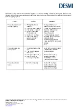
Страница 14: ...is choked 4 Suction line leaks Pump takes air 5 Suction lift too high 6 Pump and piping system wrongly dimensioned Change direction of rotation to clockwise when viewed from shaft end the direction of the arrow Clean or replace Clean the pump Find the leakage repair the fault non return valve not submerged Check data sheet Q H curve and NPSH or contact DESMI As 5 The pump uses too much power 1 Cou...

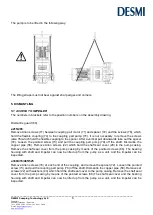
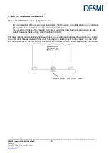
Страница 15: ...mp cannot be started unintentionally The system is to be without pressure and drained of liquid The repairman must be familiar with the type of liquid which has been pumped as well as the safety measures he is to take when handling the liquid The drain hole at the mechanical shaft seal must be inspected regularly see drawing example below Clean the drain hole as needed If the drain hole clogs up l...

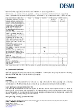
Страница 16: ...ring temperatures normally less than 85 C I Check clean if required drain hole for shaft seal I M Pumps not running Rotate pump shaft 2 to 3 revolutions or start shortly if pump is filled with liquid M Regrease pump and or motor bearings Refer to section 11 2 and motor manual if motor bearings are re greaseable Spacer coupling elastomer s I Replace mechanical shaft seal and V ring M Replace pump b...

Страница 17: ...g conditions life of 100 000 working hours and are to be relubricated according to the below table Light bearing housing combination 13 The bearings are relubricated through the lubricator nipples 84 at top and bottom of the bearing housing 18 In connection with replacement the bearings are to be mounted with the RS sealing facing downwards fill the bearing itself with grease and place a grease be...

Страница 18: ... 8000 hours 65 g Lubricated for life 80 330 100 330 125 330 100 415 125 415 100 465 Light bearing housing 4500 hours 30 g 15 g 150 330 200 330 250 330 150 415 150 465 Heavy bearing housing 4500 hours 40 g 20 g 200 415 250 415 300 415 300 418 Heavy bearing housing 4500 hours 50 g 25 g 200 525 250 525 300 525 350 525 Heavy bearing housing 4500 hours 80 g 35 g If the pump liquid temperature is below ...

Страница 19: ...pump type serial No appears on the name plate of the pump position No on the assembly drawing and designation on the spare parts list 13 OPERATING DATA The following working pressures pressure in piping incl the pressure increase caused by the pump and number of revolutions are allowed in standard pumps Pump size Max working pressure bar Bronze Cast iron Max working pressure bar SG iron Max RPM Li...

Страница 20: ...entioned max working pressure is a design value delivered pumps are pressure tested according to actual application requirements and actual flange standards For instance the above mentioned max working pressure is NOT valid for pumps approved by a classification society Pumps approved by classification societies have been pressure tested according to the requirements of these societies i e a test ...

Страница 21: ...EN 809 1998 A1 2009 Pumps and pump units for liquids Common safety requirements EN12162 2001 A1 2009 Liquid pumps Safety requirements Procedure for hydrostatic testing EN 60204 1 2006 A1 2009 Safety of machinery Electrical equipment of machines item 4 General requirements Ecodesign Directive 2009 125 EC Water pumps Commission Regulation No 547 2012 Applies only to water pumps marked with the minim...

Страница 22: ...ail desmi desmi com www desmi com 15 INFORMATION RELEVANT FOR DISASSEMBLY OR DISPOSAL AT END OF LIFE No damage materials are used in DESMI pumps please refer to DESMI Green Passport can be sent on request contact a DESMI sales office i e common recycling companies can handle the disposal at end of life Alternatively the pump and motor can be returned to DESMI at end of life for safe recycling ...

Страница 23: ...k 13 Ball bearing 14 Support disc 15 Ball bearing 16 Sunk key 17 Shaft 18 Bearing housing 19 Allen screw 20 Shaft seal cover 21 O ring 22 Allen screw 58 Copper pipe For NSLV 59 Hexagon nipple 60 Set screw 63 Bracket 64 Set screw 67 Set screw 69 Guard 70 Coupling part pump 71 Coupling part motor 72 Spacer 73 Pointed screw 74 Elastomer 76 Allen screw 77 Allen screw 79 Nut 81 Sealing washer 84 Lubric...

Страница 24: ...ing 16 Sunk key 17 Shaft 18 Bearing housing 19 Allen screw 20 Shaft seal cover 21 O ring 22 Allen screw 23 Domed cap nut 24 Spring washer 25 Stud 58 Copper pipe For NSLV 59 Hexagon nipple 60 Set screw 63 Bracket 64 Set screw 67 Set screw 69 Guard 70 Coupling part pump 71 Coupling part motor 72 Spacer 73 Pointed screw 74 Elastomer 76 Allen screw 77 Allen screw 79 Nut 81 Sealing washer 84 Lubricator...

Страница 25: ...t seal 11 Water deflector 12 Ring lock 13 Ball bearing 14 Support disc 15 Ball bearing 16 Sunk key 17 Shaft 18 Bearing housing 19 Allen screw 20 Shaft seal cover 21 O ring 22 Allen screw 23 Domed cap nut 24 Intermediate flange 25 Allen screw 26 Spring washer 27 Stud 58 Copper pipe For NSLV 59 Hexagon nipple 60 Set screw 63 Bracket 64 Set screw 67 Set screw 69 Guard 70 Coupling part pump 71 Couplin...

Страница 26: ...earing 16 Sunk key 17 Shaft 18 Bearing housing 19 Set screw 20 Shaft seal cover 21 O ring 22 Set screw 23 Lock washer 26 Cover under bearing 27 Sealing ring 2 58 Copper pipe for NSLV 59 Hexagon nipple 60 Set screw 61 Hexagon nipple 63 Bracket 64 Set screw 67 Set screw 69 Guard 70 Coupling part pump 71 Coupling part motor 72 Spacer 73 Pointed screw 74 Coupling bush 76 Allen screw 81 Sealing washer ...

Страница 27: ...ctor 12 Ring lock 13 Ball bearing 14 Grease valve ring 15 Ball bearing 16 Sunk key 17 Shaft 18 Bearing housing 19 Set screw 20 Shaft seal cover 21 O ring 22 Set screw 23 Lock washer 24 Intermediate flange 25 Allen screw 26 Cover under bearing 27 Sealing ring 2 58 Copper pipe for NSLV 59 Hexagon nipple 60 Set screw 63 Bracket 64 Set screw 67 Set screw 69 Guard 70 Coupling part pump 71 Coupling part...

Страница 28: ...lector 12 Ring lock 13 Ball bearing 14 Grease valve ring 15 Ball bearing 16 Sunk key 17 Shaft 18 Bearing housing 19 Set screw 20 Shaft seal cover 21 O ring 22 Set screw 23 Lock washer 26 Cover under bearing 27 Sealing ring 2 28 Sunk key 29 Stud 30 Domed cap nut 31 Spring washer 58 Copper pipe for NSLV 59 Hexagon nipple 60 Set screw 61 Hexagon nipple 63 Bracket 64 Set screw 67 Set screw 69 Guard 70...

Страница 29: ...using 19 Set screw 20 Shaft seal cover 21 O ring 22 Set screw 23 Lock washer 26 Cover under bearing 27 Sealing ring 2 38 Guide plate 39 Sunk screw 45 Guide plate 46 Allan screw 47 Washer 58 Copper pipe for NSLV 60 Set screw 61 Hexagon nipple 63 Bracket 64 Set screw 67 Set screw 69 Guard 70 Coupling part pump 71 Coupling part motor 72 Spacer 73 Pointed screw 74 Coupling bush 76 Allen screw 81 Seali...

Страница 30: ...Water deflector 12 Ring lock 13 Ball bearing 14 Grease valve ring 15 Ball bearing 16 Sunk key 17 Shaft 18 Bearing housing 19 Set screw 20 Shaft seal cover 21 O ring 22 Set screw 23 Lock washer 26 Cover under bearing 27 Sealing ring 2 38 Guide plate 39 Sunk screw 45 Guide plate 46 Allan screw 47 Washer 58 Copper pipe for NSLV 60 Set screw 61 Hexagon nipple 63 Bracket 64 Set screw 67 Set screw 69 Gu...

Страница 31: ...Shaft 18 Bearing housing 19 Set screw 20 Shaft seal cover 21 O ring 22 Set screw 23 Lock washer 24 Stud 26 Cover under bearing 27 Sealing ring 2 38 Guide plate 39 Sunk screw 58 Copper pipe for NSLV 59 Hexagon nipple 60 Set screw 61 Hexagon nipple 63 Bracket 64 Set screw 67 Set screw 69 Guard 70 Coupling part pump 71 Coupling part motor 72 Spacer 73 Pointed screw 74 Coupling bush 76 Allen screw 81 ...

Страница 32: ...bearing 16 Sunk key 17 Shaft 18 Bearing housing 19 Set screw 20 Shaft seal cover 21 O ring 22 Set screw 23 Lock washer 26 Cover under bearing 27 Sealing ring 2 58 Copper pipe for NSLV 59 Hexagon nipple 60 Set screw 61 Hexagon nipple 63 Bracket 64 Set screw 67 Set screw 69 Guard 70 Coupling part pump 71 Coupling part motor 72 Spacer 73 Pointed screw 74 Coupling bush 76 Allen screw 81 Sealing washer...

Страница 33: ...___________________________ DESMI Pumping Technology A S 30 Tagholm 1 9400 Nø rresundby Denmark Tel 45 96 32 81 11 Fax 45 98 17 54 99 E mail desmi desmi com www desmi com 26 DIMENSIONAL SKETCH Please require a dimensional sketch of the actual pump from DESMI ...

Страница 34: ...mping Technology A S 31 Tagholm 1 9400 Nø rresundby Denmark Tel 45 96 32 81 11 Fax 45 98 17 54 99 E mail desmi desmi com www desmi com APPENDIX A Assembly drawing of Lip seal kit in cover under bearing The lip seal kit is optional SPARE PARTS LIST 26 Cover under bearing 210 Lip Seal 211 O ring ...

Отзывы: