-10-
2. Setting up the controller & Start-up:
Shock:
It is essential that the exchanger is not subjected to thermal or mechanical shock as this could lead to
premature gasket failure.
Operation in automatic mode:
Once the pipe work and electrical connections have been made, all miniature circuit breakers (mcbs) located
in the panel should be set to “on” and the system filled and vented. The following procedure should then be
followed to start the unit:
1. The control panel should be switched on at the main isolator. The “controls healthy” lamp on the control
panel will be illuminated to indicate that the panel is live with the control voltage available.
2. Each pump is fitted with a “Hand/Off/Auto selector switch. If “Hand” is selected the relevant pump will run.
Similarly if “Off” is selected than the relevant pump will not run. If “Auto” is selected then the pump will run
under the control of the time clock/BMS interface.
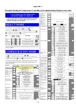
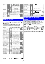
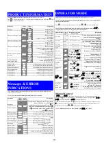
3. The temperature controller is factory set at 10% proportional span and 5 sec integral time (auto reset).
These setting should give reasonable results with most systems but, depending on the thermal response
of the system, some adjustment may be needed. Any such adjustment should only be carried out by
competent persons. Full controller instructions are given in appendix 1.
4. Adjustment of the temperature set point can be done as follows:
•
From the normal run mode press
.
•
The lower display will then show “SP” and the upper display will show the actual set point.
•
Press
or
to change the set point to the required value.
•
Finally, press
to return to normal run mode.
5. The time clock (not fitted on BMS controlled panels) is factory set to the correct day and time. Should this
need alteration this can be done by pressing and holding the CLOCK key whilst pressing the DAY, HOUR
or MIN keys until the correct values are shown.
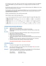
The time clock (if fitted) is also factory set to switch ON at 07.30 and OFF at 20.00 every day. Should this
need alteration this can be done as follows:
•
Press TIMER key once to enter program mode, display will show “1 ON_:__C1”
•
Press the DAY key to choose one of the 15 different day combinations (see table below) for the first
ON time of channel 1.
•
Press the HOUR and MIN keys to select the desired first ON time for Channel 1
•
Press TIMER key once. Display will show “1 OFF_:__C1”. Repeat previous steps to set the desired
first OFF time for channel 1.
•
Repeat the entire sequence to set up to four different ON/OFF times for channel 1.
•
When all required times are set press the CLOCK key to return to run mode.
NOTE: On panels fitted with a time clock, twin head pump(s), and auto head change over, channel two on
the time clock is used within the panel to rotate the duty pump and should not be altered from factory
settings. Should this inadvertently be done then it must be re-programmed as follows:
•
Set the times for channel 1 as described above, once this is complete press the TIMER key so the
display shows “1ON_:__C2”.
•
Press the DAY key until 14 is selected.
•
Set the ON time to 00.01 using the HOUR and MIN keys.
•
Press the TIMER key so display shows “1OFF_:__C2”.
•
Set the OFF time to 23.59.
•
Press CLOCK key to return to run mode.
Содержание UKE-8-50
Страница 3: ... 3 ...
Страница 9: ... 9 ...
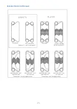
Страница 13: ... 13 Examples of Gasket and Plate types ...


