U.S. Boiler Company LE Series Скачать руководство пользователя страница 42

42

 103626-04 - 3/18

XII.  TROUBLESHOOTING

A.

  COMBUSTION

1.  NOZZLES — Although the nozzle is a relatively 

inexpensive device, its function is critical to the 

successful operation of the oil burner. The selection 

of the nozzle supplied with the LE boiler is the 

result of extensive testing to obtain the best flame 

shape and efficient combustion. Other brands of the 

same spray angle and spray pattern may be used but 

may not perform at the expected level of CO

2

 and 

smoke. Nozzles are delicate and should be protected 

from dirt and abuse. Nozzles are mass-produced and 

can vary from sample to sample. For all of those 

reasons a spare nozzle is a desirable item for a 

serviceman to have.

2.  FUEL  LEAKS — Any fuel leak between the pump 

and the nozzle will be detrimental to good combus-

tion results. Look for wet surfaces in the air tube, 

under the ignitor, and around the air inlet. Any such 

leaks should be repaired as they may cause erratic 

burning of the fuel and in the extreme case may 

become a fire hazard.

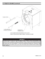
3.  SUCTION LINE LEAKS — Any such leaks should 

be repaired, as they may cause erratic burning of the 

fuel and in extreme cases may become a fire hazard.  

Whatever it takes, 

The Oil Must Be Free of Air

.  

This can be a tough problem, but it must be re-

solved.  Try bleeding the pump through a clear tube.  

There must be no froth visible.  There are various 

test kits available to enable you to look at the oil 

through clear tubing adapted to the supply line at the 

pump fitting.  Air eliminators are on the market that 

have potential.  Also, electronic sight glasses are 

being used with good success.  At times, new tubing 

must be run to the tank or new fittings put on.  Just 

make sure you get the air out before you leave.

  Any air leaks in the fuel line will cause an unstable 

flame and may cause delayed ignition noises.  Use 

only flare fittings in the fuel lines.

4.  GASKET  LEAKS — If 11.5 to 12.5% CO

2

 with a 

#1 smoke cannot be obtained in the breeching, look 

for air leaks around the burner mounting gasket, 

observation door, and canopy gasket. Such air leaks 

will cause a lower CO

2

 reading in the breeching. The 

smaller the firing rate the greater effect an air leak 

can have on CO

2

 readings.

5.  DIRT — A fuel filter is a good investment. Acciden

-

tal accumulation of dirt in the fuel system can clog 

the nozzle or nozzle strainer and produce a poor 

spray pattern from the nozzle. The smaller the firing 

rate, the smaller the slots become in the nozzle and 

the more prone to plugging it becomes with the 

same amount of dirt.

6.  WATER — Water in the fuel in large amounts will 

stall the fuel pump. Water in the fuel in smaller 

amounts will cause excessive wear on the pump, but 

more importantly water doesn’t burn. It chills the 

flame and causes smoke and unburned fuel to pass 

out of the combustion chamber and clog the 

flueways of the boiler.

7.  COLD  OIL — If the oil temperature approaching 

the fuel pump is 40°F or lower, poor combustion or 

delayed ignition may result.  Cold oil is harder to 

atomize at the nozzle. Thus, the spray droplets get 

larger and the flame shape gets longer. An outside 

fuel tank that is above grade or has fuel lines in a 

shallow bury is a good candidate for cold oil. The 

best solution is to locate the tank near the boiler in 

the basement utility room or bury the tank and lines 

deep enough to keep the oil above 40°F.  Check 

environmental issues with local authorities having 

jurisdiction.

8.  FLAME  SHAPE — Looking into the combustion 

chamber through the observation port, the flame 

should appear straight with no sparklers rolling up 

toward the crown of the chamber. If the flame drags 

to the right or left, sends sparklers upward or makes 

wet spots on the target wall, the nozzle should be 

replaced. If the condition persists look for fuel leaks, 

air leaks, water or dirt in the fuel as described above.

9.  HIGH  ALTITUDE  INSTALLATIONS — Air 

openings must be increased at higher altitudes. Use 

instruments and set for 11.5 to 12.5% CO

2

.

10.  START-UP  NOISE — Late ignition is the cause of 

start-up noises. If it occurs recheck for electrode 

settings, flame shape, air or water in the fuel lines.

11.  SHUT  DOWN  NOISE — If the flame runs out of 

air before it runs out of fuel, an after burn with noise 

may occur. That may be the result of a faulty cut-off 

valve in the fuel pump, or it may be air trapped in the 

nozzle line. It may take several firing cycles for that 

air to be fully vented through the nozzle. Water in the 

fuel or poor flame shape can also cause shut down  

noises.

NOTICE

CHECK TEST PROCEDURE. A very good test for 

isolating fuel side problems is to disconnect the 

fuel system and with a 24" length of tubing, fire 

out of an auxiliary five gallon pail of clean, fresh, 

warm #2 oil from another source. If the burner runs 

successfully when drawing out of the auxiliary 

pail then the problem is isolated to the fuel or fuel 

lines being used on the jobsite.

Содержание LE Series

Страница 1: ...OIL FIRED BOILER For service or repairs to boiler call your heating contractor When seeking information on boiler provide Boiler MOdel Number and Serial Number as shown on Rating Label Boiler Model N...

Страница 2: ...safety devices D All wiring on boilers installed in the USA shall be made in accordance with the National Electrical Code and or Local Regulations DANGER Indicates an imminently hazardous situation w...

Страница 3: ...or to see that all controls are correctly installed and are operating properly when installation is complete including verifying that the limit sensor is fully installed seated in bottom of Well Failu...

Страница 4: ...ed before the start of the heating season for any obstructions A clean and unobstructed chimney flue is necessary to allow noxious fumes that could cause injury or loss of life to vent safely and will...

Страница 5: ...5 103626 04 3 18 I GENERAL INFORMATION Figure 1A LE Packaged Water Boiler with Beckett AFG Burner...

Страница 6: ...6 103626 04 3 18 I GENERAL INFORMATION continued Figure 1B LE Packaged Water Boiler with Riello 40F Burner...

Страница 7: ...INFORMATION Boiler Model Water Capacity Gallons Approximate Shipping Weight LBS Minimum Chimney Requirements Round In Dia Rectangle In x In Height Ft LE1L 6 1 325 6 8 x 8 15 Notes 1 MBH refers to tho...

Страница 8: ...erican National Standard NFPA 31 Standard for the Installation of Oil Burning Equipment NOTE 2 LE Series boilers can be installed in rooms with clearances from combustible material as listed above Lis...

Страница 9: ...unconfined space of a conven tionally constructed building the fresh air infiltration through cracks around windows and doors normally provides adequate air for combustion and ventilation 5 For boile...

Страница 10: ...hing holes in Spacer Tubesheet or Door See Figure 4 Tighten all hex nuts and cap screws by hand only 7 Replace door assembly Hinge brackets attached to door must rest on top of hinge brackets attached...

Страница 11: ...on front of L7248L Control Mount Control on factory installed immersion well located in center tapping on top of boiler with L7248L Boiler Control Transformer Relay Control Center Harness Assembly on...

Страница 12: ...12 103626 04 3 18 Figure 5B Relief Valve and Boiler Control Assembly Details Riello 40F Burner Figure 6 Limit Sensor Insertion III PACKAGED BOILER ASSEMBLY TRIM AND CONTROLS continued...

Страница 13: ...circulator to supply sufficient flow GPM to allow a 20 F temperature differential in the system When sizing the system circulator the pressure drop of all radiators baseboard and radiant tubing and a...

Страница 14: ...14 103626 04 3 18 IV WATER PIPING AND TRIM continued Figure 8A Recommended Water Piping for Circulator Zoned Heating Systems Supply Side Circulator...

Страница 15: ...15 103626 04 3 18 IV WATER PIPING AND TRIM continued Figure 8B Recommended Water Piping for Zone Valve Zoned Heating Systems Supply Side Circulator...

Страница 16: ...G Installation is NOT complete unless a safety relief valve is installed as shown in Figure 8A or 8B Safety relief valve discharge piping must be piped near floor to eliminate potential of severe burn...

Страница 17: ...e burned and sends less heat up the chimney A new boiler probably has a higher efficiency than the boiler being replaced That probably means that the stack temperature from the new boiler will be lowe...

Страница 18: ...18 103626 04 3 18 V VENTING continued Figure 9 Recommended Smoke Pipe Arrangement and Chimney Requirements Figure 10 Draft Regulator Locations...

Страница 19: ...er jacket junction boxes and or control boxes 3 Use armored cable BX over all exposed line voltage wiring 4 If an indirect water heater is used use priority zoning DO NOT use priority zoning for Hydro...

Страница 20: ...4 3 18 VI ELECTRICAL continued Figure 11A Schematic Wiring Diagram Cold Start Control with Beckett AFG Burner REFER TO FIGURE 12 FOR SCHEMATIC WIRING DIAGRAM OF APPROPRIATE BURNER AND OIL PRIMARY CONT...

Страница 21: ...3 18 VI ELECTRICAL continued Figure 11B Schematic Wiring Diagram Cold Start Control with Riello 40 Series Burner REFER TO FIGURE 12 FOR SCHEMATIC WIRING DIAGRAM OF APPROPRIATE BURNER AND OIL PRIMARY C...

Страница 22: ...PRIATE STEAM OR WATER BOILER CONTROL SCHEMATIC REFER TO FIGURES 11A AND 11B NOTE APPLY THIS BURNER SCHEMATIC TO APPROPRIATE STEAM OR WATER BOILER CONTROL SCHEMATIC REFER TO FIGURES 11A AND 11B Figure...

Страница 23: ...pression fittings 4 Use of a high efficiency micron filter Garber or equivalent in addition to conventional filter is highly recommended B SINGLE PIPE OIL LINES 1 Standard burners are provided with si...

Страница 24: ...0 31 100 11 26 100 12 21 83 13 62 14 41 Lift H See Figure Maximum Length of Tubing H R See Figure 3 8 OD Tubing 3 GPH 1 2 OD Tubing 3 GPH 0 93 100 2 85 100 4 77 100 6 69 100 8 60 100 10 52 100 12 44 1...

Страница 25: ...d expansion tank g Allow water to overflow from bucket until discharge from hose is bubble free for 30 seconds h When zone valve is completely purged of air close zone valve or shut off valve Open zon...

Страница 26: ...air band and air shutter settings Readjust if necessary see Burner Specifications Table 5 e OPEN ALL SHUT OFF VALVES in the oil supply line to the burner f ATTACH A PLASTIC HOSE TO FUEL PUMP VENT BLEE...

Страница 27: ...PTER 2 from the DRAWER ASSEMBLY by loosening the SCREW 1 ii Remove existing nozzle from nozzle adapter iii Insert the proper NOZZLE into NOZZLE ADAPTER and tighten securely DO NOT cover tighten refer...

Страница 28: ...sure was factory pre set but must be checked at time of burner start up A pressure gauge is attached to the PRESSURE BLEEDER PORT 7 for pressure readings Two PIPE CONNECTORS 4 are supplied with the bu...

Страница 29: ...L BURNER WHILE OPERATING flame present 1 ADJUST DRAFT REGULATOR for a draft of zero to maximum of 03 water gauge in the breeching after chimney has reached operating temperature and while burner is ru...

Страница 30: ...cycling the burner operation about 5 to 10 times will rid oil line of this air 2 IF NOZZLE CONTINUES TO DRIP repeat Paragraph H Step 1 above If this does not stop the dripping remove cut off valve an...

Страница 31: ...ugged from the control and the resistance measured with a meter in the conventional way Conduct these tests with flame present see chart below Flame Detection Range Normal 0 1600 ohms Limited 1600 ohm...

Страница 32: ...mit setting The burner should shut down and circulators continue running c Allow the temperature to drop below control setting The burner must restart d Boiler installation is not considered complete...

Страница 33: ...Orientation c When the thermostat calls for heat the boiler control starts the system circulator and the thermal purge circulator pre purge time begins If the time is completed or boiler temperature i...

Страница 34: ..._ The Boiler Control is factory programmed with a High Limit Setpoint of 180 F The boiler turns off when the boiler water temperature bt is above this value The High Limit setpoint is adjustable betwe...

Страница 35: ...n 140 Start with no delay TT on 140 Start after 2 minute delay ZR on ZC_ ZR 140 Start with no delay ZR on ZC_ ZR 140 Start after 2 minute delay ZR on ZC_ DH 140 Start with no delay ZR on ZC_ DH 140 St...

Страница 36: ...ses a call for heat and energizes the System Circulator output to service heating zone 1 A second zone s thermostat may be wired to the ZR input to energize heating zone 2 circulator wired to the ZC o...

Страница 37: ...leaned and refilled as previously described test the pH of the water in the system This can easily be done by drawing a small sample of boiler water and testing with hydrion paper which is used in the...

Страница 38: ...all corners 3 Always keep the manual fuel supply valve shut off if the burner is shut down for an extended period of time 4 To recondition the heating system in the fall season after a prolonged shut...

Страница 39: ...sary BE CAREFUL not to damage liner or rear door insulation piece Inspect front and rear door insulation pieces front door gaskets and combustion chamber liner for damage Replace any damaged pieces im...

Страница 40: ...iler is connected to a dirty or inadequate chimney The interior of the chimney flue must be inspected and cleaned before the start of the heating season and should be inspected periodically throughout...

Страница 41: ...rator 2 Long sleeved loose fitting clothing 3 Gloves 4 Eye Protection Take steps to assure adequate ventilation Wash all exposed body areas gently with soap and water after contact Wash work clothes s...

Страница 42: ...oor spray pattern from the nozzle The smaller the firing rate the smaller the slots become in the nozzle and the more prone to plugging it becomes with the same amount of dirt 6 WATER Water in the fue...

Страница 43: ...ablished within 15 seconds of oil valve actuation known as Trial For Ignition TFI lockout will occur Lockout is indicated by a red LED solid on located on the oil primary control Hard Lockout will occ...

Страница 44: ...ered during safety output relay check sequence or un powered during running or powered in idle in combination with water temperature above 264 F limit Cycle power to the control Replace control if pro...

Страница 45: ...oiler Company Wholesale distributor Should you require assistance in locating a U S Boiler Company Distributor in your area or have questions regarding the availability of U S Boiler Company products...

Страница 46: ...46 103626 04 3 18 XIII REPAIR PARTS continued Figure 27 LE Bare Boiler Assembly...

Страница 47: ...ded in 108137 01 4E Front Door and Furnace Rope Gasket 1 Included in 108137 01 4F 6 x 3 4 Drive Screw 2 80860718 5A Hinge Bracket 4 7022701 5B Hinge Spacer 2 7303310 5C Hinge Pin 2 80861614 5D Hairpin...

Страница 48: ...48 103626 04 3 18 XIII REPAIR PARTS continued Figure 28 LE Boiler Jacket Insulation...

Страница 49: ...R8239A1052 Control Center Transformer Relay Required on Riello Burner Applications Only 1 80160235 2 Honeywell 123871A 3 4 NPT x 3 1 80160452 3 Conbraco 10 408 05 3 4 FPT 30 PSI Relief Valve 1 816603...

Страница 50: ...ENT OIL BURNER PARTS CONTACT YOUR WHOLESALER OR THE BURNER MANUFACTURER R W BECKETT CORP 38251 CENTER RIDGE RD P O BOX 1289 ELYRIA OHIO 1 800 645 2876 44036 XIII REPAIR PARTS continued FIGURE 30 BECKE...

Страница 51: ...w Firing Rate Baffle Kit 5880 Spline Nut Bulkhead 3666 Connector Tube Assembly 5394 Electrode Clamp 149 Electrode Clamp Screw 4219 Electrode Insulator Assembly Kit 5780 Nozzle Line LT Assembly Less He...

Страница 52: ...l Burners C6501010 for an exploded view of the burner and a list of spare parts Riello Corporation of America 35 Pond Park Road Hingham Massachusetts 02043 Telephone 617 749 8292 Facsimile 617 740 206...

Страница 53: ...sed to connect the probe LWCO to the supply or return piping as shown below Select the appropriate size tee using the LWCO manufacturer s instructions Often the branch connection must have a minimum d...

Страница 54: ...y be used if the boiler manufacturer has provided piping and wiring connections and instructions to allow for this application How to Test Shut off fuel supply Lower water level until water level is B...

Страница 55: ...y Side Circulator Section V Venting Figure 9 18 Recommended Smoke Pipe Arrangement and Chimney Requirements Figure 10 18 Draft Regulator Locations Section VI Electrical Figure 11A 20 Schematic Wiring...

Страница 56: ...on Chamber Section XIII Repair Parts Figure 27 46 LE Bare Boiler Assembly Figure 28 48 LE Boiler Jacket Insulation Figure 29 49 LE Boiler Trim Controls Figure 30 50 Beckett AFG Oil Burner Repair Parts...

Страница 57: ...cations Table 6 26 Riello 40F Burner Specifications Section IX Operating Table 7 33 Sequence of Operation Table 8 35 Circulator Pre purge Time Example Parameter PP_ 2 Minutes Table 9 35 Domestic Hot W...

Страница 58: ...58 103626 04 3 18...

Страница 59: ...59 103626 04 3 18...

Страница 60: ...60 103626 04 3 18 U S Boiler Company Inc P O Box 3020 Lancaster PA 17604 1 888 432 8887 www usboiler net...

Отзывы: