U.S. Boiler Company LE Series Скачать руководство пользователя страница 34

34

 103626-04 - 3/18

IX.  OPERATING (continued)

  Press and release the 

I

” 

key on the Boiler Control 

to change from one parameter to the next.  Each 

setting will alternately flash between the relevant 

display code and its corresponding value.

Operating Mode Options

t

Status Numbers:

 Standby

 Running



 Self Test)

bt

Boiler Temperature

P

Operating Setpoint (Outdoor Reset)

HL

High Limit Setting

HdF

High Limit Differential

hr

Heat Request Status

dh

DHW Request Status

Err

Boiler Error

  For example, when the “

I

” key is pressed on the 

Boiler Control until “

bt

” is displayed, it will then 

flash a three digit number (such as “

0

”) followed 

by either “

F

” (or “

C

”).  This indicates that the boiler 

water temperature is


180°F.  Other operating 

parameters display the information in a similar 

fashion.

  Please note that in operating mode to hold the 

display on the value the user can press and hold 

either the Up 

ñ

 or Down 

ò

 keys and the value will 

be continuously shown. This may be helpful in 

watching a value “live”.

4. 

Changing the Adjustable Parameters

   To adjust parameters such as the High Limit 

Setpoint and High Limit Differential:
a.  Using the Boiler Control display, access the 

adjustment mode by pressing and holding the Up 

ñ

, Down 

ò

, and “

I

” keys simultaneously for 

three (3) seconds.  This procedure is intended to 

discourage unauthorized changes or accidental 

changes to limit settings.

b.  Press the “

I

” key to display available Adjust-

ment Mode options. Select an option.

c.  Press the Up 

ñ

 and Down 

ò

 keys to adjust the 

displayed setpoint to the desired value.

d.  To return to the normal operating mode from the 

Adjustment Mode, when the “

bc

” option is 

displayed, press either the Up 

ñ

 or Down 

ò

  key.  

If no keys are pressed, after five (5) minutes the 

Boiler Control will automatically return to the 

Operating Mode.

5. 

More Information about Adjustable Parameters


a.  High Limit (

HL_

)

  The Boiler Control is factory programmed with a 

High Limit Setpoint of 180

°

F.  The boiler turns 

“off” when the boiler water temperature (

bt

) is 

above this value.  The High Limit setpoint is 

adjustable between 140

° 

and 240

°

F.  The 

Operating Setpoint (

P

) will equal the High 

Limit Setpoint.

b.  High Limit Differential (

HdF

)

  The Cold Start Boiler Control is factory pro-

grammed with a Differential of 15

°

F.  The 

Differential is the number of degrees the boiler 

temperature must decrease below the Operating 

Setpoint before the boiler can restart.  The 

differential is adjustable between 10

° 

and 30

°

F.

c.  Circulator Overrun Time (

OR_

)

  Circulator Overrun Time (also called “circulator 

off delay” or “circulator post purge”) continues 

circulator operation after a call for heat has 

ended, sending excess heat from the boiler into 

the priority zone.  Ensure system piping and zone 

panel settings allow water flow to the priority 

zone after the call for heat ends.  The  Circulator 

Overrun Time has a factor setting of 0 minutes 

and is field adjustable between 0 and 10 minutes.

d.  Circulator Pre-Purge Time (

PP_

)

  When the boiler is warm [boiler water tempera-

ture higher than 140°F (adjustable using Start 

Temperature parameter)] and there is a thermo-

stat call for heat, the system circulator is started 

and boiler firing is delayed pre-purge minutes. If 

the temperature drops below 140°F or there is a 

DHW Call for Heat the boiler is started without 

delay.  Additionally, the boiler is started without 

delay if the thermostat call for heat is initiated 

when the boiler water temperature is less than 

140°F.  This feature helps save energy by 

satisfying home heating needs with residual 

Cold Start Boiler Control

Adjustment Mode Options

HL_

140-240°F

Adjust High Limit Setting

HdF

10-30°F

Adjust High Limit Differential

ZC_

dh

ZR

 or 

ELL

ZC and ZR Terminal Function

Or_

0-10 minutes

Pump Overrun Time

PP_

2-20 minutes

Pump Pre-purge Time

t_

140 - 180°F

Start Temperature

Pt_

On

 or 

Off

Priority Time

f-C

F

 or 

C

Select degrees F or C Mode

bac

Back to Operating Mode

Содержание LE Series

Страница 1: ...OIL FIRED BOILER For service or repairs to boiler call your heating contractor When seeking information on boiler provide Boiler MOdel Number and Serial Number as shown on Rating Label Boiler Model N...

Страница 2: ...safety devices D All wiring on boilers installed in the USA shall be made in accordance with the National Electrical Code and or Local Regulations DANGER Indicates an imminently hazardous situation w...

Страница 3: ...or to see that all controls are correctly installed and are operating properly when installation is complete including verifying that the limit sensor is fully installed seated in bottom of Well Failu...

Страница 4: ...ed before the start of the heating season for any obstructions A clean and unobstructed chimney flue is necessary to allow noxious fumes that could cause injury or loss of life to vent safely and will...

Страница 5: ...5 103626 04 3 18 I GENERAL INFORMATION Figure 1A LE Packaged Water Boiler with Beckett AFG Burner...

Страница 6: ...6 103626 04 3 18 I GENERAL INFORMATION continued Figure 1B LE Packaged Water Boiler with Riello 40F Burner...

Страница 7: ...INFORMATION Boiler Model Water Capacity Gallons Approximate Shipping Weight LBS Minimum Chimney Requirements Round In Dia Rectangle In x In Height Ft LE1L 6 1 325 6 8 x 8 15 Notes 1 MBH refers to tho...

Страница 8: ...erican National Standard NFPA 31 Standard for the Installation of Oil Burning Equipment NOTE 2 LE Series boilers can be installed in rooms with clearances from combustible material as listed above Lis...

Страница 9: ...unconfined space of a conven tionally constructed building the fresh air infiltration through cracks around windows and doors normally provides adequate air for combustion and ventilation 5 For boile...

Страница 10: ...hing holes in Spacer Tubesheet or Door See Figure 4 Tighten all hex nuts and cap screws by hand only 7 Replace door assembly Hinge brackets attached to door must rest on top of hinge brackets attached...

Страница 11: ...on front of L7248L Control Mount Control on factory installed immersion well located in center tapping on top of boiler with L7248L Boiler Control Transformer Relay Control Center Harness Assembly on...

Страница 12: ...12 103626 04 3 18 Figure 5B Relief Valve and Boiler Control Assembly Details Riello 40F Burner Figure 6 Limit Sensor Insertion III PACKAGED BOILER ASSEMBLY TRIM AND CONTROLS continued...

Страница 13: ...circulator to supply sufficient flow GPM to allow a 20 F temperature differential in the system When sizing the system circulator the pressure drop of all radiators baseboard and radiant tubing and a...

Страница 14: ...14 103626 04 3 18 IV WATER PIPING AND TRIM continued Figure 8A Recommended Water Piping for Circulator Zoned Heating Systems Supply Side Circulator...

Страница 15: ...15 103626 04 3 18 IV WATER PIPING AND TRIM continued Figure 8B Recommended Water Piping for Zone Valve Zoned Heating Systems Supply Side Circulator...

Страница 16: ...G Installation is NOT complete unless a safety relief valve is installed as shown in Figure 8A or 8B Safety relief valve discharge piping must be piped near floor to eliminate potential of severe burn...

Страница 17: ...e burned and sends less heat up the chimney A new boiler probably has a higher efficiency than the boiler being replaced That probably means that the stack temperature from the new boiler will be lowe...

Страница 18: ...18 103626 04 3 18 V VENTING continued Figure 9 Recommended Smoke Pipe Arrangement and Chimney Requirements Figure 10 Draft Regulator Locations...

Страница 19: ...er jacket junction boxes and or control boxes 3 Use armored cable BX over all exposed line voltage wiring 4 If an indirect water heater is used use priority zoning DO NOT use priority zoning for Hydro...

Страница 20: ...4 3 18 VI ELECTRICAL continued Figure 11A Schematic Wiring Diagram Cold Start Control with Beckett AFG Burner REFER TO FIGURE 12 FOR SCHEMATIC WIRING DIAGRAM OF APPROPRIATE BURNER AND OIL PRIMARY CONT...

Страница 21: ...3 18 VI ELECTRICAL continued Figure 11B Schematic Wiring Diagram Cold Start Control with Riello 40 Series Burner REFER TO FIGURE 12 FOR SCHEMATIC WIRING DIAGRAM OF APPROPRIATE BURNER AND OIL PRIMARY C...

Страница 22: ...PRIATE STEAM OR WATER BOILER CONTROL SCHEMATIC REFER TO FIGURES 11A AND 11B NOTE APPLY THIS BURNER SCHEMATIC TO APPROPRIATE STEAM OR WATER BOILER CONTROL SCHEMATIC REFER TO FIGURES 11A AND 11B Figure...

Страница 23: ...pression fittings 4 Use of a high efficiency micron filter Garber or equivalent in addition to conventional filter is highly recommended B SINGLE PIPE OIL LINES 1 Standard burners are provided with si...

Страница 24: ...0 31 100 11 26 100 12 21 83 13 62 14 41 Lift H See Figure Maximum Length of Tubing H R See Figure 3 8 OD Tubing 3 GPH 1 2 OD Tubing 3 GPH 0 93 100 2 85 100 4 77 100 6 69 100 8 60 100 10 52 100 12 44 1...

Страница 25: ...d expansion tank g Allow water to overflow from bucket until discharge from hose is bubble free for 30 seconds h When zone valve is completely purged of air close zone valve or shut off valve Open zon...

Страница 26: ...air band and air shutter settings Readjust if necessary see Burner Specifications Table 5 e OPEN ALL SHUT OFF VALVES in the oil supply line to the burner f ATTACH A PLASTIC HOSE TO FUEL PUMP VENT BLEE...

Страница 27: ...PTER 2 from the DRAWER ASSEMBLY by loosening the SCREW 1 ii Remove existing nozzle from nozzle adapter iii Insert the proper NOZZLE into NOZZLE ADAPTER and tighten securely DO NOT cover tighten refer...

Страница 28: ...sure was factory pre set but must be checked at time of burner start up A pressure gauge is attached to the PRESSURE BLEEDER PORT 7 for pressure readings Two PIPE CONNECTORS 4 are supplied with the bu...

Страница 29: ...L BURNER WHILE OPERATING flame present 1 ADJUST DRAFT REGULATOR for a draft of zero to maximum of 03 water gauge in the breeching after chimney has reached operating temperature and while burner is ru...

Страница 30: ...cycling the burner operation about 5 to 10 times will rid oil line of this air 2 IF NOZZLE CONTINUES TO DRIP repeat Paragraph H Step 1 above If this does not stop the dripping remove cut off valve an...

Страница 31: ...ugged from the control and the resistance measured with a meter in the conventional way Conduct these tests with flame present see chart below Flame Detection Range Normal 0 1600 ohms Limited 1600 ohm...

Страница 32: ...mit setting The burner should shut down and circulators continue running c Allow the temperature to drop below control setting The burner must restart d Boiler installation is not considered complete...

Страница 33: ...Orientation c When the thermostat calls for heat the boiler control starts the system circulator and the thermal purge circulator pre purge time begins If the time is completed or boiler temperature i...

Страница 34: ..._ The Boiler Control is factory programmed with a High Limit Setpoint of 180 F The boiler turns off when the boiler water temperature bt is above this value The High Limit setpoint is adjustable betwe...

Страница 35: ...n 140 Start with no delay TT on 140 Start after 2 minute delay ZR on ZC_ ZR 140 Start with no delay ZR on ZC_ ZR 140 Start after 2 minute delay ZR on ZC_ DH 140 Start with no delay ZR on ZC_ DH 140 St...

Страница 36: ...ses a call for heat and energizes the System Circulator output to service heating zone 1 A second zone s thermostat may be wired to the ZR input to energize heating zone 2 circulator wired to the ZC o...

Страница 37: ...leaned and refilled as previously described test the pH of the water in the system This can easily be done by drawing a small sample of boiler water and testing with hydrion paper which is used in the...

Страница 38: ...all corners 3 Always keep the manual fuel supply valve shut off if the burner is shut down for an extended period of time 4 To recondition the heating system in the fall season after a prolonged shut...

Страница 39: ...sary BE CAREFUL not to damage liner or rear door insulation piece Inspect front and rear door insulation pieces front door gaskets and combustion chamber liner for damage Replace any damaged pieces im...

Страница 40: ...iler is connected to a dirty or inadequate chimney The interior of the chimney flue must be inspected and cleaned before the start of the heating season and should be inspected periodically throughout...

Страница 41: ...rator 2 Long sleeved loose fitting clothing 3 Gloves 4 Eye Protection Take steps to assure adequate ventilation Wash all exposed body areas gently with soap and water after contact Wash work clothes s...

Страница 42: ...oor spray pattern from the nozzle The smaller the firing rate the smaller the slots become in the nozzle and the more prone to plugging it becomes with the same amount of dirt 6 WATER Water in the fue...

Страница 43: ...ablished within 15 seconds of oil valve actuation known as Trial For Ignition TFI lockout will occur Lockout is indicated by a red LED solid on located on the oil primary control Hard Lockout will occ...

Страница 44: ...ered during safety output relay check sequence or un powered during running or powered in idle in combination with water temperature above 264 F limit Cycle power to the control Replace control if pro...

Страница 45: ...oiler Company Wholesale distributor Should you require assistance in locating a U S Boiler Company Distributor in your area or have questions regarding the availability of U S Boiler Company products...

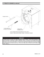
Страница 46: ...46 103626 04 3 18 XIII REPAIR PARTS continued Figure 27 LE Bare Boiler Assembly...

Страница 47: ...ded in 108137 01 4E Front Door and Furnace Rope Gasket 1 Included in 108137 01 4F 6 x 3 4 Drive Screw 2 80860718 5A Hinge Bracket 4 7022701 5B Hinge Spacer 2 7303310 5C Hinge Pin 2 80861614 5D Hairpin...

Страница 48: ...48 103626 04 3 18 XIII REPAIR PARTS continued Figure 28 LE Boiler Jacket Insulation...

Страница 49: ...R8239A1052 Control Center Transformer Relay Required on Riello Burner Applications Only 1 80160235 2 Honeywell 123871A 3 4 NPT x 3 1 80160452 3 Conbraco 10 408 05 3 4 FPT 30 PSI Relief Valve 1 816603...

Страница 50: ...ENT OIL BURNER PARTS CONTACT YOUR WHOLESALER OR THE BURNER MANUFACTURER R W BECKETT CORP 38251 CENTER RIDGE RD P O BOX 1289 ELYRIA OHIO 1 800 645 2876 44036 XIII REPAIR PARTS continued FIGURE 30 BECKE...

Страница 51: ...w Firing Rate Baffle Kit 5880 Spline Nut Bulkhead 3666 Connector Tube Assembly 5394 Electrode Clamp 149 Electrode Clamp Screw 4219 Electrode Insulator Assembly Kit 5780 Nozzle Line LT Assembly Less He...

Страница 52: ...l Burners C6501010 for an exploded view of the burner and a list of spare parts Riello Corporation of America 35 Pond Park Road Hingham Massachusetts 02043 Telephone 617 749 8292 Facsimile 617 740 206...

Страница 53: ...sed to connect the probe LWCO to the supply or return piping as shown below Select the appropriate size tee using the LWCO manufacturer s instructions Often the branch connection must have a minimum d...

Страница 54: ...y be used if the boiler manufacturer has provided piping and wiring connections and instructions to allow for this application How to Test Shut off fuel supply Lower water level until water level is B...

Страница 55: ...y Side Circulator Section V Venting Figure 9 18 Recommended Smoke Pipe Arrangement and Chimney Requirements Figure 10 18 Draft Regulator Locations Section VI Electrical Figure 11A 20 Schematic Wiring...

Страница 56: ...on Chamber Section XIII Repair Parts Figure 27 46 LE Bare Boiler Assembly Figure 28 48 LE Boiler Jacket Insulation Figure 29 49 LE Boiler Trim Controls Figure 30 50 Beckett AFG Oil Burner Repair Parts...

Страница 57: ...cations Table 6 26 Riello 40F Burner Specifications Section IX Operating Table 7 33 Sequence of Operation Table 8 35 Circulator Pre purge Time Example Parameter PP_ 2 Minutes Table 9 35 Domestic Hot W...

Страница 58: ...58 103626 04 3 18...

Страница 59: ...59 103626 04 3 18...

Страница 60: ...60 103626 04 3 18 U S Boiler Company Inc P O Box 3020 Lancaster PA 17604 1 888 432 8887 www usboiler net...

Отзывы: