background image

Level & Install Unit

15

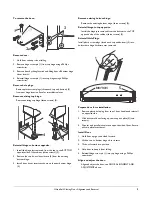
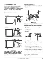
12 Level The Unit

Leveling Information

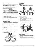
It is recommended that the unit is level.

1. Use a level to check 

the levelness of the 
unit from front to 
back and from side 
to side. Level should 
be placed along top 
edge and side edge 
as shown 

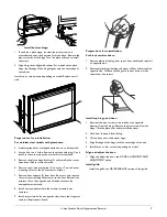
2. If the unit is not level, adjust the feet on the corners of the unit 

as necessary (not available in CO29 models).

3. Check the levelness after each adjustment and repeat the 

previous steps until the unit is level.

INSTALLATION TIP

If the room floor is higher than the floor in the cut-out opening, 
adjust the rear feet to achieve a total unit rear height of 1/8" less 
than the opening’s rear height. Shorten the unit height in the front 
by adjusting the front feet. This allows the unit to be gently tipped 
into the opening. Readjust the front feet to level the unit after it is 
correctly positioned in the opening.

1

Turn Foot to Adjust

13 Install the Unit

Installation 

1. Open the water supply valve in the main water source.

2. Plug in the power cord.

CLR2160 & CLRCO2175 Only

• Open the door and press the POWER icon. to turn the unit 

OFF. 

Note: If the unit is NOT turned OFF, water will immediately 
start flowing into the unit when it is first plugged into the 
electrical outlet. 

• Test the drain system by pouring one gallon of water into 

the ice bin. The water should drain freely and there should 
be no leakage.

All Models

3. Gently push the unit into position. Be careful not to kink the 

water supply line or entangle the electrical cord.

4. Re-check the leveling, from front to back and side to side. Make 

any necessary adjustments. The unit’s top surface should be 
approximately 1/8" below the counter top.

5. Remove the tape from the glass shelves and wipe out the inside 

of the unit with a clean, water-dampened cloth.

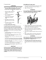
Relocating the Shelves

Both the glass shelves in the refrigerator and the inner door 
shelves can be moved to accommodate your bottles, cans and 
containers.

Glass Shelves on Right-Hand Hinge Units

• Open door fully, grasp shelf firmly, lift front edge slightly, and 

pull straight out.

• Choose new location and slide shelf onto the appropriate rib.

Glass Shelves on Left-Hand Hinge Units

• Pull shelf out about 6” to clear the wall’s molded protrusion.
• Tilt right-hand edge of shelf up.
• Keeping at this angle and hugging the right wall, pull the shelf 

out.

• Choose new location and insert over ribs, tilting right-hand 

edge up. Push in, then lower shelf onto ribs.

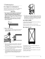
Door Shelves

• First pull shelf up at a 45° angle, then straight out (see Figure 

39).

• Choose new location and line up on bosses. First push straight 

in, then down at a 45° angle.

Содержание CLR2160

Страница 1: ...The Built In Undercounter Leader Since 1962 CLEAR ICE MODELS CLEAR ICE COMBO MODELS ICE COMBO MODELS U LINE COM CO1175 CO2175 CLR2160 CLRCO2175 INSTALL GUIDE CO29...

Страница 2: ...ment and Adjustment 6 Door Reversability 6 Reversing the door 6 Self Closing Doors Door Alignment and Adjustment 8 Door Reversability 8 Reversing the door 8 Door Panel Installation Custom 1 4 Thick Do...

Страница 3: ...cal Grounding Required Never attempt to repair or perform maintenance on the unit until the electricity has been disconnected Never remove the round grounding prong from the plug and never use a two p...

Страница 4: ...Panel Kit Part number U OL2175B black units U OL2175W white units A complete water hook up kit is also available for purchase from your dealer Order U Line Part No WATERHOOKUP Exterior Cleaning Black...

Страница 5: ...lations CLR2160 Series Follow the cut out drawing The 15 1 4 width allows 1 4 for ease in installation and removal of the unit 24 is the cabinet depth in most installations 8 24 Minimum 24 1 4 See Ele...

Страница 6: ...16 34 3 16 15 15 Black and White Stainless Steel 23 1 4 3 7 8 23 1 4 3 15 16 Add 3 4 To Depth For Drain Line Clearance Add 3 4 To Depth For Drain Line Clearance CO1175 Series BLACK CO1175 23 5 16 34...

Страница 7: ...ments The units are designed to operate between 50 F 10 C and 100 F 37 C High ambient temperatures 100 F 37 C or higher may reduce the unit s ability to reach low temperatures and may also reduce the...

Страница 8: ...h black and white doors are field reversible Stainless steel models with glass doors without locks are field reversible Stainless steel models without glass doors must be ordered right or left hand hi...

Страница 9: ...ure to only remove the two screws holding the actuator to the door Reinstall the actuator 4 on the opposite end of the door where the nameplate was removed 8 Install new nameplate where the actuator a...

Страница 10: ...sets 3 Turn the door upside down and inspect the hinge plate mounting holes The plate has slotted mounting holes Loosen but do not remove the two hinge plate screws 1 4 If door edge opposite the hinge...

Страница 11: ...r inserts as shown on the new bottom hinge 4 Remove existing bottom hinge Remove the existing bottom hinge three screws 2 Reinstall hinge to top opposite Install the hinge just removed from the bottom...

Страница 12: ...tilting forward and lifting off bottom hinge pin 2 Pull door gasket out of groove top edge of door only Start in the middle and pull outward moving toward the edge This may take some force Model Width...

Страница 13: ...een placed by a qualified electrician The unit requires a grounded and polarized 115 VAC 60 Hz 15A power supply normal household current An individual properly grounded branch circuit or circuit break...

Страница 14: ...n using the two wrenches Drain Connection CLR2160 CLRCO2175 IMPORTANT IMPORTANT Drain can NOT be located directly below unit Unit has a solid base that will not allow the unit to drain below itself We...

Страница 15: ...r cabinet or attempt to touch any components except the discharge tube during testing 4 Check that the clamps and hose connections are tight at the following areas Discharge tube A Drain tube B Vent t...

Страница 16: ...event of a pump failure It must have an operating temperature range of 50 F to 110 F 10 C to 40 C IMPORTANT IMPORTANT In the event of a power outage restricted drain or pump failure the failure to us...

Страница 17: ...st plugged into the electrical outlet Test the drain system by pouring one gallon of water into the ice bin The water should drain freely and there should be no leakage All Models 3 Gently push the un...

Страница 18: ...ution A The hinges should be self closing when the door is open approximately 8 If this is not the case make sure the closers at the bottom of the hinge pin are clean greased and installed correctly A...

Страница 19: ...today The Milwaukee Wisconsin based family operated business provides continuity and vision from which innovations continue to be born Going forward U Line will continue offering best in class product...

Отзывы: