


SARA-G3 series - System Integration Manual
UBX-13000995 - R06
Objective Specification
Design-in
Page 146 of 218
2.6.1.3
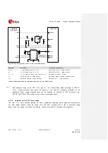
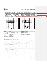
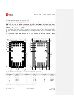
Guidelines for external analog audio device connection circuit design
The differential analog audio input / output can be used to connect the module to an external analog
audio device. Audio devices with a differential analog input / output are preferable, as they are more
immune to external disturbances.
describe the application circuits, following the suggested circuit
design-in.
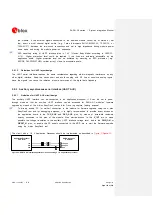
Guidelines for the connection to a differential analog audio input:
The
SPK_P
/
SPK_N
balanced output of the module must be connected to the differential input of
the external audio device by means of series capacitors for DC blocking (e.g. 10 µF Murata
GRM188R60J106M) to decouple the bias present at the module output, as described in the left side
of
Guidelines for the connection to a single ended analog audio input:
A proper differential to single ended circuit must be inserted from the
SPK_P
/
SPK_N
balanced
output of the module to the single ended input of the external audio device, as described in the right
side of
: 10 µF series capacitors (e.g. Murata GRM188R60J106M) are provided
to decouple the bias present at the module output, and a voltage divider is provided to properly adapt
the signal level from the module output to the external audio device input
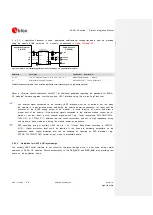
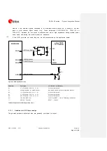
Guidelines for the connection to a differential analog audio output:
The
MIC_P
/
MIC_N
balanced input of the module must be connected to the differential output of the
external audio device by means of series capacitors for DC blocking (e.g. 10 µF Murata
GRM188R60J106M) to decouple the bias present at the module input, as described in the left side of
Guidelines for the connection to a single ended analog audio output:
A proper single ended to differential circuit has to be inserted from the single ended output of the
external audio device to the
MIC_P
/
MIC_N
balanced input of the module, as described in the right
: 10 µF series capacitors (e.g. Murata GRM188R60J106M) are provided
to decouple the bias present at the module input, and a voltage divider is provided to properly adapt
the signal level from the external audio device output to the module input
Additional guidelines for any connection:
The DC-block series capacitor acts as high-pass filter for audio signals, with cut-off frequency
depending on both the values of capacitor and on the input impedance of the device. For example: in
case of differential input impedance of 600
, the two 10 µF capacitors will set the -3 dB cut-off
frequency to 53 Hz, while for single ended connection to 600
external device, the cut-off
frequency with just the single 10 µF capacitor will be 103 Hz. In both cases the high-pass filter has
a low enough cut-off to not impact the audio signal frequency response
Use a suitable power-on sequence to avoid audio bump due to charging of the capacitor: the final
audio stage should be always enabled as last one
Formatted:
English (U.S.)
Formatted:
English (U.S.)
Formatted:
English (U.S.)
Formatted:
English (U.S.)