SARA-G3 series - System Integration Manual
UBX-13000995 - R06
Objective Specification
System description
Page 61 of 218
show examples of common scenarios and timing constraints:
AT+UPSV=2 power saving configuration is active and the timeout from last data received to idle-mode
start is set to 2000 frames due to the timeout previously set by AT+UPSV=1,2000 as the default
case
Hardware flow control disabled on the DCE (as required to enable the AT+UPSV=2 configuration) and
RTS
line set to OFF by the DTE: in this case the
CTS
line is set by the module accordingly to its
power saving configuration as illustrated in
, like for the AT+UPSV=1 case with HW
flow control enabled
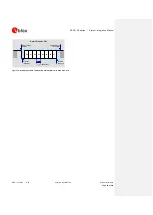
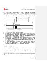
shows the case where the DCE UART is disabled and only a wake-up is forced. In
this scenario the only character sent by the DTE is the wake-up character; as a consequence, the DCE
UART is disabled when the timeout from last data received expires (2000 frames without data reception,
as the default case).
CTS OFF
CTS ON
DCE UART is enabled for 2000 GSM frames (~9.2 s)
time
Wake up time: ~20 ms
time
TxD
module
input
Wake up character
Not recognized by DCE
Figure 20: Wake-up via data reception without further communication

