SARA-G3 series - System Integration Manual
UBX-13000995 - R06
Objective Specification
System description
Page 74 of 218
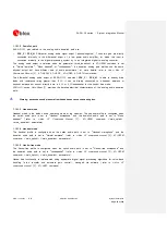
The pin configured to provide the “General purpose output” function is set as
o
Output / Low, if the parameter <gpio_out_val> of AT+UGPIOW command is set to 0
o
Output / High, if the parameter <gpio_out_val> of AT+UGPIOW command is set to 1
Pad disabled
:
All the GPIOs can be configured in tri-state with an internal active pull-down enabled, as a not used
pin, setting the parameter <gpio_mode> of +UGPIOC AT command to 255.
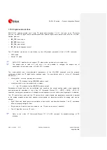
The “Pad disabled” mode can be provided on more than one pin per time: it is possible to
simultaneously set the same mode on another pin (also on all the GPIOs).
The pin configured to provide the “Pad disabled” function is set as
o
Tri-state with an internal active pull-down enabled
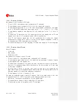
describes the configurations of all SARA-G350 GPIO pins.
Pin Module
Name
Description
Remarks
16
SARA-G350
GPIO1
GPIO
By default, the pin is configured as Pad disabled.
Can be alternatively configured by the AT+UGPIOC command as
Output
Input
Network Status Indication
GNSS Supply Enable
GSM Tx Burst Indication
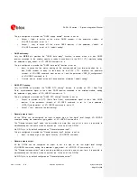
23 SARA-G350
GPIO2
GPIO
By default, the pin is configured to provide GNSS Supply Enable
function.
Can be alternatively configured by the +UGPIOC command as
Output
Input
Network Status Indication
Pad disabled
24 SARA-G350
GPIO3
GPIO
By default, the pin is configured to provide GNSS Data Ready
function.
Can be alternatively configured by the +UGPIOC command as
Output
Input
Network Status Indication
GNSS Supply Enable
Pad disabled
25 SARA-G350
GPIO4
GPIO
By default, the pin is configured to provide GNSS RTC sharing
function.
Can be alternatively configured by the +UGPIOC command as
Output
Input
Network Status Indication
GNSS Supply Enable
Pad disabled
Table 11: GPIO pins configurations


