


SARA-G3 series - System Integration Manual
UBX-13000995 - R06
Objective Specification
Design-in
Page 147 of 218
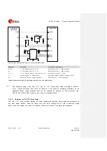
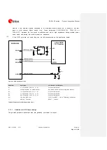
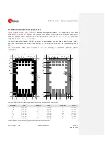
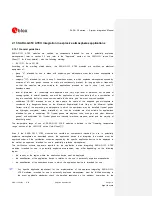
The signal levels can be adapted by setting gain using AT commands (refer to the
u-blox AT
, +USGC, +UMGC), but additional circuitry must be inserted if the
SPK_P
/
SPK_N
output level of the module is too high for the input of the audio device or if the output
level of the audio device is too high for
MIC_P
/
MIC_N
, as the voltage dividers present in the
circuits described in the right side of
to properly adapt the signal level
SARA-G350
C1
C2
45
SPK_N
44
SPK_P
GND
49
M IC_P
GND
Analog IN (-)
Analog IN (+)
Analog OUT (-)
Analog OUT (+)
Audio Device
GND
GND
48
M IC_N
C3
C4
SARA-G350
45
SPK_N
44
SPK_P
GND
49
M IC_P
GND
Analog IN
Audio Device
GND
Reference
48
M IC_N
Analog OUT
C5
C6
R2
R1
R4
R3
C7
C8
46
M IC_BIAS
47
M IC_GND
46
M IC_BIAS
47
M IC_GND
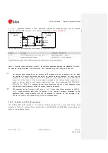
Figure 59: Application circuits to connect the module to audio devices with proper differential or single-ended input/output
Reference
Description
Part Number – Manufacturer
C1, C2, C3, C4,
C5, C6, C7, C8
10 µF Capacitor X5R 0603 5% 6.3 V
GRM188R60J106M – Murata
R1, R3
0
Ω
Resistor 0402 5% 0.1 W
RC0402JR-070RL – Yageo Phycomp
R2, R4
Not populated
Table 35: Connection to an analog audio device
2.6.1.4
Guidelines for analog audio layout design
Accurate analog audio design is very important to obtain clear and high quality audio. The GSM signal
burst has a repetition rate of 217 Hz that lies in the audible range. A careful layout is required to reduce
the risk of noise from audio lines due to both
VCC
burst noise coupling and RF detection.
Guidelines for the uplink path, which is the most sensitive since the analog input signals are in the
microVolts range, are the following:
Avoid coupling of any noisy signal to microphone lines: it is strongly recommended to route microphone
lines away from module
VCC
supply line, any switching regulator line, RF antenna lines, digital lines
and any other possible noise source
Keep ground separation from microphone lines to other noisy signals. Use an intermediate ground layer
or vias wall for coplanar signals
Route microphone signal lines as a differential pair embedded in ground to reduce differential noise
pick-up. The balanced configuration will help reject the common mode noise
Route microphone reference as a signal line since the
MIC_GND
pin is internally connected to ground
as a sense line as the reference for the analog audio input
Cross other signals lines on adjacent layers with 90° crossing
Formatted:
English (U.S.)
Formatted:
English (U.S.), Do not
check spelling or grammar