background image

http://www.TYAN.com 

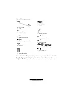
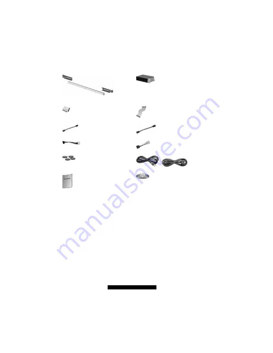
And the following accessories: 


P/N 451715600031 
1×  rail kit 


P/N 343728700001 
1×  heatsink 


1×  primary IDE cable 


1×  secondary IDE cable 


1×  primary serial ATA cable 


1×  secondary serial ATA cable 


1×  HDD power to pinheader cable 


2×  SATA power cable 


4×  rubber feet 


2×  power cord (USA and Germany) 


1×  B5103 User’s Manual 


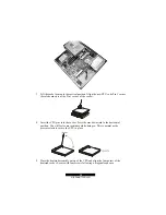
1×  TYAN driver CD 


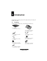
Inspect all the items. If any item is damaged or missing, notify your dealer immediately. 

Keep the shipping carton and packing materials in case you need to ship or store the 
computer in the future. 


Содержание B5103G12S2

Страница 1: ...demark of Promise Technology ATI ATI RAGE is a trademark of ATI Technologies Incorporated Winbond is a trademark of Winbond Electronics Corporation Portable Document Format PDF is a trademark of Adobe Corporation Information contained in this document is furnished by TYAN Computer Corporation and has been reviewed for accuracy and reliability prior to printing TYAN assumes no liability whatsoever ...

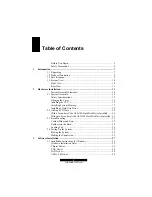
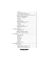
Страница 2: ... CPU 15 Installing System Memory 17 Installing a Hard Disk Drive 18 2 2 Adding a CD Drive 20 With a Secondary Ultra ATA 100 Hard Disk Drive Installed 20 Without a Secondary Ultra ATA 100 Hard Disk Drive Installed 21 2 3 Rack Mounting 22 Cabinet Slides and Ears 22 Cabinet into the Rack 24 Locking Tab 24 2 4 Setting Up the System 25 Placing the System 25 Making the Connection 25 3 Software Installat...

Страница 3: ...Floppy Drive Usage 39 3 4 Installation Instructions for Solaris 9 39 Solaris 9 Installation Notes 39 LAN Driver 39 4 Using the LCD Console 41 4 1 Configuring the System 41 Before You Begin 41 4 2 Setting the Configuration for Windows 42 4 3 Setting the Configuration for Linux 45 4 4 Setting the Configuration for FreeBSD 48 5 BIOS Setup 51 5 1 BIOS Setup Program 51 Starting BIOS Setup 51 Main Menu ...

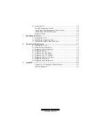
Страница 4: ...nsion Card 72 7 3 Adding a Secondary Hard Disk Drive 73 8 System Parts Replacement 77 8 1 Opening the Cover 77 8 2 Removing the Front Bezel 78 8 3 Replacing the Button Board 78 8 4 Replacing the Fan 79 8 5 Replacing the USB Board 80 8 6 Replacing the LCD Module 80 8 7 Replacing the Power Supply 81 8 8 Replacing the Blower 82 8 9 Replacing the Motherboard 82 9 Appendix 85 Caution Text Conserning Li...

Страница 5: ...the connected equipment and ensure that you have over current protection l Do not disable the power cord ground feature This equipment was designed to connect to a grounded earthed power outlet The grounding plug is an important safety feature l Ensure that the power outlet is located or installed near the equipment and is easily accessible l Do not allow anything to rest on the power cord Do not ...

Страница 6: ......

Страница 7: ... MiSERVER WS112R case kit P N 411728700101 pre installed 1 S5103GNNR motherboard P N 411715600005 pre installed 1 LCD module P N 411715600004 pre installed 1 button board P N 411728700106 pre installed 1 USB board P N 422715600051 pre installed 2 fan assembly 40 28 mm P N 422707400033 pre installed 1 fan assembly 50 10 mm blower P N 471172400027 pre installed 1 power supply 1U ATX 300 W P N 411715...

Страница 8: ... ATA cable 1 secondary serial ATA cable 1 HDD power to pinheader cable 2 SATA power cable 4 rubber feet 2 power cord USA and Germany 1 B5103 User s Manual 1 TYAN driver CD Inspect all the items If any item is damaged or missing notify your dealer immediately Keep the shipping carton and packing materials in case you need to ship or store the computer in the future ...

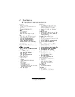
Страница 9: ... via COM2 Four direction buttons plus one Select and one Cancel button Two USB 2 0 ports Networking Two 1000Base T 100Base TX and 10Base T Ethernet LAN ports Intel 82541GI and 82547GI controllers Supports TCP UDP IPv4 Checksum off load Storage Capacity Up to two PATA HDDs or two SATA HDDs SATA HDDs support RAID0 RAID1 for Windows 2000 XP Integrated Hardware Monitoring ADT7463 CPU temperature and v...

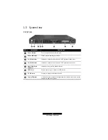
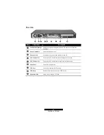
Страница 10: ... network connection on LAN1 external connection LAN2 Indicator Indicates a network connection on LAN2 internal connection Hard Disk Drive Indicator Indicates activity on the hard disk drive USB Ports Each of the two ports connects a USB device LCD Screen Displays messages and values entered Control Buttons Allow you to enter network configuration information reboot the system and power down the sy...

Страница 11: ...r cord Ž Power Switch Turns the main power of the system on and off LAN1 Connector Connects the LAN cable for internal network connection LAN2 Connector Connects the LAN cable for external network connection Serial Port Connects a serial device VGA Port Connects an external CRT monitor USB Ports Each of the two ports connects a USB device Expansion Slot Allow you to install a PCI card ...

Страница 12: ......

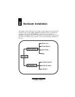
Страница 13: ...ble each component of the system Rack Mounting section describes the procedures for mounting the system into the rack You can use the system assembly flowchart and the chart next to determine the proper sequence for removing or installing components to the server System Assembly Rack Mounting Cabinet Cover CPU and Heatsink Hard Disk Drive Cabinet Rails and Ears Cabinet into the Rack Locking Tab DI...

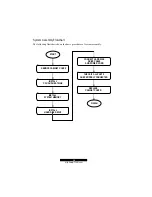
Страница 14: ...wchart shows the basic procedures of system assembly FINISH START INSTALL SYSTEM MEMORY REMOVE CABINET COVER INSTALL CPU AND HEATSINK INSTALL HARD DISK DRIVE CONNECT HARD DISK DRIVE CABLE AND POWER CORD CHECK IF ALL PARTS ARE PROPERLY CONNECTED REPLACE CABINET COVER ...

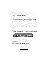
Страница 15: ...l Before you install any option turn all power switches off Unplug all power cords from the system and all peripherals Leaving the power on can cause serious damage to your system l If the system is mounted on an equipment rack remove the system from the rack and take it to a service area Do not attempt to disassemble the system while it is still in the equipment rack Opening the Cover 1 Remove tw...

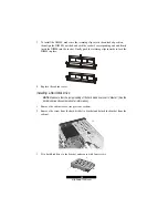
Страница 16: ...socket 4 Insert the CPU pins into the socket Press the arm downward to the horizontal position You will feel some resistance while doing so This is normal as the pressure starts to secure the CPU in place 5 Place the heatsink assembly on top of the CPU and align the four points of the heatsink socket Secure with four screws following a diagonal sequence ...

Страница 17: ...le sockets to support a maximum of 4 GB You must follow these requirements for the DIMM to be used with the system l Unbuffered DDR SDRAM Double Data Rate Synchronous DRAM with ECC l PC2100 PC2700 PC3200 compliant l 2 5 V Follow this procedure to install a DIMM 1 Open the cabinet cover see previous section 2 Locate the DIMM sockets ...

Страница 18: ...ng clips inwards to lock the DIMM in place 4 Replace the cabinet cover Installing a Hard Disk Drive NOTE Make sure that the jumper setting of the hard disk drive is set to Master See the hard disk drive s documentation for information 1 Remove the cabinet cover see previous section 2 Remove the screw from the hard disk drive bracket and detach the bracket from the cabinet 3 Fit a hard disk drive t...

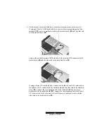
Страница 19: ...a cable to the primary IDE connector on the motherboard Œ and the other end to the hard disk drive If using a Serial ATA hard disk drive connect the included Serial ATA data cable to the primary SATA connector on the motherboard and the other end to the hard disk drive Œ Connect the corresponding end of the included HDD power to pin header cable to the motherboard connect the corresponding end of ...

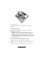
Страница 20: ... and connector pins CAUTION Follow the instructions in this section carefully The DVD or CD drive contains a laser device Do not attempt to open the DVD or CD drive s enclosure or remove a DVD or CD drive using any procedures other than those contained in this section to avoid the risk of exposure to harmful radiation With a Secondary Ultra ATA 100 Hard Disk Drive Installed 1 Remove the cabinet co...

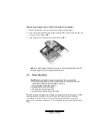
Страница 21: ...ling the system in an equipment rack make sure that l The ambient temperature around the system which may be higher than the room temperature is within the limits specified in section 1 2 l There is sufficient airflow around the unit l Electrical circuits are not overloaded l The equipment is properly grounded l Do not place any objects on top of the system The slide rack mount kit provides a slid...

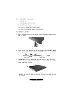
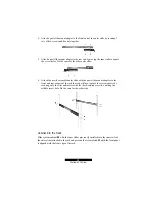
Страница 22: ...of the cabinet Then secure each with two screws 2 Detach the inner slide from the outer slide by pressing on the release latch Œ and pulling apart the inner slide from the outer slide Do the same for the other slide 3 Align the inner slide s first round screw hole with the screw hole on the system chassis beside the mounting ears and attach the screw together with next screw hole Do the same for t...

Страница 23: ...bled outer slide with the post slide mount adapters to the front and rear corners of the rack that you will use to place the system chassis by securing only the first and last screw holes dark colored screws omitting the middle screw hole Do the same for the other side Cabinet into the Rack Slide system cabinet Œ with the inner slides previously installed into the inner rails of the outer slides a...

Страница 24: ...k that uses a Web browser Netscape Navigator or Microsoft Internet Explorer version 4 0 or later l Network parameters including IP address for the system the subnet mask of your network and a gateway router address if communicating with other networks l Third party software applications if not supplied or pre installed Placing the System You can either place the system on a flat surface a desk or ...

Страница 25: ... to the system and the other end to an electrical outlet 4 Connect the display monitor s D type signal connector to the system s VGA port Then plug one end of the monitor s power cord into the power socket on the monitor and the other end to an electrical outlet Turn on the monitor before turning on the system 5 Connect a USB keyboard to the system s USB port 6 Switch on I the main power switch on...

Страница 26: ...the system The hard disk drive spins up the fan turns on and the LCD screen lights up A number of status messages are displayed on the screen during the boot process CAUTION It is important to follow the proper power down procedure for turning off the system ...

Страница 27: ...ported are shown on the next table Driver OS Available on CD Windows 2000 ü Windows 2000 SBS ü Windows 2003 ü Windows 2003 SBS ü Windows XP ü RedHat Linux 9 0 ü SuSE Linux 8 1 ü Turbo Linux 8 ü LCD driver FreeBSD 4 7 ü Windows 2000 ü Windows 2000 SBS ü Windows 2003 ü Windows 2003 SBS ü Windows XP ü RedHat Linux 9 0 ü SuSE Linux 8 1 Not Available Turbo Linux 8 Not Available Watchdog driver FreeBSD ...

Страница 28: ...t Standard Format 2 0 SDK FreeBSD 4 7 Not Available Windows 2000 ü Windows 2000 SBS ü Windows 2003 Not Available Windows 2003 SBS Not Available Windows XP ü RedHat Linux 9 0 Not Available SuSE Linux 8 1 Not Available Turbo Linux 8 Not Available RAID function FreeBSD 4 7 Not Available NOTE The driver CD may have been updated after this User s Manual was completed If your CD is different from that d...

Страница 29: ...containing the Intel RAID driver into the USB floppy drive 6 Specify the Intel 82801ER SATA RAID Controller to install 7 Then proceed with the Windows operating system installation After installing the Windows operating system proceed to the following driver installations NOTE An autorun program is provided on the driver CD to help you easily install the drivers As you insert the CD the autorun pr...

Страница 30: ...w be loaded USB v 2 0 Driver 1 Insert the driver CD into the CD drive 2 For Windows 2000 Install Windows 2000 Service Pack 4 from the Microsoft official web site at http www microsoft com windows2000 downloads servicepacks sp4 default asp For Windows XP Install Windows XP Service Pack 1 from the Microsoft official web site at http www microsoft com windowsxp pro downloads service packs sp1 sp1lang...

Страница 31: ...TA RAID items then save and exit Setup 3 Insert the driver CD into the CD drive 4 For Windows 2000 Download and install the q812415_W2K_SP4_x86_EN exe program from the Microsoft Official Web site http www microsoft com downloads details aspx FamilyID c9b3cd31 1dd5 45bc 806f 3f347e558008 DisplayLang en For Windows XP Download and install the q812415_WXP_SP2_x86_ENU exe program from the Microsoft Of...

Страница 32: ...to the driver location at ASF Windows driver Watchdog AsfDeviceChecked inf and click on Open OK When installation asks for the CD just click on OK and browse the path again to ASF Windows driver Watchdog then click on Open OK to finish the Watchdog driver installation 4 Run the install bat program in the ASF Windows service directory 5 Restart the Windows ASF Alert Standard Format 2 0 SDK 1 Insert...

Страница 33: ... system but if you are using a 3 2 GHz CPU with your system add the following boot parameter apm off acpi off to allow the system to support USB devices If you are using the SMP kernel in order to allow a complete system shutdown then perform the following 1 Modify the boot grub menu lst by changing the boot parameter apm power_off acpi off Then save and exit 2 Run the command grub install dev hda...

Страница 34: ...tar unzip archive tar zxf e1000 5 2 16 tar gz 4 Change to the driver src directory cd e1000 5 2 16 src 5 Compile the driver module make install The binary will be installed as lib modules KERNEL_VERSION kernel drivers net e1000 o The installation locations listed above are the default ones They might not be correct for certain Linux distributions For more information refer to the ldistrib txt file...

Страница 35: ...the driver usually informs the hardware Watchdog that everything is in order and it should reset the system after a little while If userspace should fail e g RAM error kernel bug etc the notification ceases and the hardware Watchdog resets the system reboot after the timeout occurs 1 Insert the driver CD into the CD drive 2 Copy wddm x x tar gz of the ASF Linux watchdog directory to the directory ...

Страница 36: ...tup Load Setup defaults and set the CD drive as the primary boot device then save and exit the BIOS Setup 2 Connect the USB keyboard and mouse to your system s rear USB ports 3 Insert the FreeBSD 4 7 Installer disc 1 to the CD drive and press Enter quickly or press any key for the command prompt 4 On the Kernel Configuration Menu select Start kernel configuration in CLI mode 5 On the config prompt...

Страница 37: ... example use home username em or usr local src em 3 Untar unzip the archive tar xvfz em x x x tar gz This will create an em x x x directory 4 To create a loadable module perform the following steps a To compile the module cd em x x x make b To install the compiled module in the system directory make install c If you want the driver to load automatically when the system is booted 1 Follow steps a a...

Страница 38: ...P_address 7 Verify that the interface works Enter the following where IP_address is the IP address for another machine on the same subnet as the interface that is being tested ping IP_address 8 To configure the IP address to remain after rebooting edit etc rc conf and create the appropriate ifconfig_em interface_num entry ifconfig_em interface_num ifconfig_settings Sample usage ifconfig_em0 inet 1...

Страница 39: ...al Solaris 9 operating system installation but since Serial ATA controllers are not compatible with IDE Parallel ATA controllers they need a different driver that is not included in the Solaris 9 installation kernel Solaris 9 cannot be installed on a Serial ATA hard disk drive normally LAN Driver 1 Insert the driver CD into the CD drive 2 Copy INTCGigaE pkg of the LAN Intel LINUX SOLARIS directory...

Страница 40: ......

Страница 41: ...begin make sure that you have the following information ready l IP address assigned to the system l Subnet mask of your network l Gateway router address necessary only if communicating with other networks The LCD screen on the front of the system displays two lines of text The first line shows the information required the second line shows the data already entered You can enter the data by using t...

Страница 42: ...ch succeeding press of the Right arrow the following prompt appears allowing you to configure the network NIC Choice default is First NIC Enable DHCP default is Yes IP Address Netmask Gateway DNS Server Using New Setting Down arrow once 1 Restart Upon pressing the Right arrow the following prompt appears allowing you to restart the system Do you want to reset Press the Right arrow to restart the s...

Страница 43: ...ch succeeding press of the Right arrow the value of the following appear depending on your settings under Performance List Configure down arrow seventh time see below Do you want to display default is Yes CPU Usage Memory Load Total Memory Avail Memory NIC1 Traffic NIC2 Traffic Total HardDisk Used HardDisk Down arrow six 6 times HW Monitor List Configure Upon each succeeding press of the Right arr...

Страница 44: ... Avail Memory NIC1 Traffic NIC2 Traffic Total HardDisk Used HardDisk Down arrow eight 8 times Urgency Alert Upon each succeeding press of the Right arrow the following prompt appear allowing you to enable urgency alert Do you want to change Send Power Down Send Event Log default is No You can check under Program Administrative Tools Event Viewer Application Log when an alert occur NOTE If you pres...

Страница 45: ...ow once 1 Restart Upon pressing the Right arrow the following prompt appears allowing you to restart the system Restart Press S Select to restart the system Down arrow twice 2 Shut Down Upon pressing the Right arrow the following prompt appears allowing you to shutdown the system Shutdown Press S Select to shutdown the system Down arrow three 3 times Reset Admin Password Upon pressing the Right ar...

Страница 46: ...ing on your settings under Performance List Configure down arrow ninth time see below Perfor Display default is Yes CPU Usage Memory Usage Disk Usage ETH0 Flow Speed ETH1 Flow Speed Down arrow seven 7 times Urgency Alert Upon pressing the Right arrow the following prompt appears allowing you to enable urgency alert Enable Alert default is Yes Press S Select to enable urgency alert Down arrow eight...

Страница 47: ...w Speed ETH1 Flow Speed Down arrow ten 10 times Alert Choice Upon pressing the Right arrow the following prompt appears allowing you to select the system s alert method Which Alert default is System log Press the Down arrow to choose the shutdown alert method Press S Select to enable your choice of system alert method You can check the file LCD alert_log_file when an alert occurs NOTE If you press...

Страница 48: ...Server Using New Setting Press S Select to accept Down arrow once 1 Restart Upon pressing the Right arrow the following prompt appears allowing you to restart the system Restart Press S Select to restart the system Down arrow twice 2 Shut Down Upon pressing the Right arrow the following prompt appears allowing you to shutdown the system Shutdown Press S Select to shutdown the system Down arrow thr...

Страница 49: ...ding on your settings under Performance List Configure down arrow ninth time see below Perfor Display default is Yes CPU Usage Memory Usage Disk Usage em0 Flow Speed em1 Flow Speed Down arrow seven 7 times Urgency Alert Upon pressing the Right arrow the following prompt appears allowing you to enable urgency alert Enable Alert default is Yes Press S Select to enable urgency alert Down arrow eight ...

Страница 50: ...Speed em1 Flow Speed Down arrow ten 10 times Alert Choice Upon pressing the Right arrow the following prompt appears allowing you to select the system s alert method Which Alert default is System log Press the Down arrow to choose the shutdown alert method Press S Select to enable your choice of system alert method You can check the file var log alert_log_file when an alert occurs NOTE If you pres...

Страница 51: ...or settings on your computer may differ l The Setup program may have been updated after the publication of this manual l The settings you select in your operating system might override similar settings in Setup To run BIOS Setup make sure that you have connected a USB keyboard and display monitor to your system Then press F2 when the prompt appears in the screen during system startup The prompt sh...

Страница 52: ...en of various system information while booting QuickBoot Mode sets if the system will skip certain tests while booting This will decrease the time needed to boot the system Memory Frequency Shows the current frequency of system memory Memory Channel Shows the current channel mode of system memory System Memory Shows the total memory on your system Extended Memory Shows the total extended memory on...

Страница 53: ...nlocked processor If the processor s frequency multiple is locked you will not see this item Advanced Processor Options APIC Interrupt Routing turns on and initializes I O APIC Advanced Programmable Interrupt Controller Compatible FPU Code enables or disables FPU Floating Point Unit I O Device Configuration Serial Port A B Base I O Address and Interrupt Sets the input output address and Interrupt ...

Страница 54: ...used by the operating system Power Saving sets the power saving mode Standby Timeout sets the timer for the system to enter Standby mode when it has been idle for the set time period Resume On Time Resume Time allows the system to wake up at a specific time Power Button Behavior sets the desired system power state when the power button is pressed After Power Failure sets the mode of operation if t...

Страница 55: ...t Boot Menu The Boot menu allows you to set the priority of the booting devices There are four possible devices l Removable Devices l Hard Drive l CD ROM l IBA GE Slot 0208 v1216 LAN Intel 82547GI Use the up or down arrow key to select a device and press the plus key to move the device upward or minus key to move it downward Exit Menu The Exit menu contains the ways of exiting the Setup program Ex...

Страница 56: ... jumper location and the table that follow for jumper definition CAUTION Jumpers not described in this section are reserved for factory use only Do not change the default settings Jumper Definition Setting Description 1 2 Normal default J2 CMOS setting 2 3 Clear CMOS To clear the RTC and CMOS RAM set J2 to 2 3 for one second and set it back to 1 2 again ...

Страница 57: ...ve Drive SLED Your system provides the Intel Application Accelerator for creating your array There are two types of array architectures that you can create l RAID 0 In this type data is split across drives resulting in higher data throughput Performance is good but the failure of any disk in the array results in data loss This type is commonly referred to as striping l RAID 1 Recommended In this t...

Страница 58: ...er 3 Also you need to install two Serial ATA disk drives to the motherboard refer to chapter 7 2 Boot up with Windows 2000 or Windows XP 3 Run the Intel Application Accelerator program 4 Create your desired array See the following subsections for details Creating an Array for Performance RAID 0 1 Select RAID then Create Volume Manually ...

Страница 59: ...59 http www TYAN com 2 Select RAID 0 under the item Select RAID Level then click on Next 3 Click on Yes Y to continue ...

Страница 60: ...60 http www TYAN com 4 Click on Create to create the new RAID volume 5 Click on OK to finish ...

Страница 61: ...YAN com Creating a Security Array RAID 1 1 With the Intel Application Accelerator program running select RAID then click on Create Volume Manually 2 Select RAID 1 under the item Select RAID Level then click on Next ...

Страница 62: ...62 http www TYAN com 3 Click on Yes Y to continue 4 Click on Yes Y to continue ...

Страница 63: ...me 6 Click on OK to finish Creating RAID With an Existing Data Drive Use this method if you have a Serial ATA disk drive that already contains data or is the boot device in your system You will need another Serial ATA disk drive of identical or larger storage capacity ...

Страница 64: ...rator program running select RAID then click on Create Volume from Existing Disk 2 Select a source disk then click on Next 3 Then follow the steps outlined in the previous sections Creating an Array for Performance RAID 0 and Creating a Security Array RAID 1 ...

Страница 65: ... operating system running Set Up Management Console Using another system set up the ASF 2 0 Management Console and perform the steps outlined next to install the following programs 1 Insert the driver CD into the CD drive 2 For ASF Proxy Run the setup exe file in the ASF console proxy directory For Proxy SDK Run the proxySDK exe file in the ASF console SDK directory Then copy the ASFMgmtConsole ex...

Страница 66: ...ddress ipconfig and ping 2 Run the alertAPP exe file located on the Agent s system and log in directly without having to type anything then check that the following configurations are set correctly Check the option Enable ASF Select the correct adapter Enter the correct Management Console s address The Alerting Enabled Status indicator should light ...

Страница 67: ...67 http www TYAN com 3 Run the ASFMgmtConsole exe file on the Management Console then check if the data from the Agent is correct ...

Страница 68: ...68 http www TYAN com Obtain Traps and Push Messages 1 Run AlertApp to set Heartbeat 2 Run ASFMgmtConsole to obtain Alert from the Agent ...

Страница 69: ... Remote Control 1 To generate Key from Management Console run ASFMgmtConsole to generate the Administrator Key 2 Save the Key from Management Console into a floppy disk 3 Run AlertApp to load the Security Key to the Agent ...

Страница 70: ...70 http www TYAN com 4 Run AlertApp to select the Remote Control functions supported by the system 5 Run ASFMgmtConsole to select and execute Remote Control operations send secured RMCP ...

Страница 71: ...touching a protective grounding device or unpainted metal on the rear panel of the system before unplugging the power cord l Before you install any option turn all power switches off Unplug all power cords from the system and all peripherals Leaving the power on can cause serious damage to your system l If the system is mounted on an equipment rack remove the system from the rack and take it to a ...

Страница 72: ...se a PCI expansion card to add to the system make sure that the card is less than 7 inches 177 8 mm long Otherwise it will not fit into place 2 Open the cabinet cover see the previous section in this chapter 3 Remove the screw lift the small retainer and then the metal slot cover Keep the cover for future use when you remove the card 4 Firmly press the expansion card s edge connector into the expa...

Страница 73: ...isk drive Ultra ATA 100 or Serial ATA type It is advised that you select a hard disk drive that meets the following specifications A hard disk drive that does not meet these specifications can cause reliability problems in your system l Peak current draw must not exceed 1 8 amperes maximum at 5 volts and 0 7 amperes maximum at 12 volts l Rotational speed 5400 7200 rpm l Interface Ultra ATA 100 or ...

Страница 74: ...e secondary IDE connector see figure above and the other end to the rear of the hard disk drive Then connect the power cord If using a Serial ATA hard disk drive connect one end of the included Serial ATA data cable to the secondary Serial ATA connector and the other end to the rear of the hard disk drive Œ Connect the corresponding end of the included Serial ATA power cord to the end of the exist...

Страница 75: ...75 http www TYAN com 6 You can create RAID for the hard disk drives see Chapter 6 for information ...

Страница 76: ......

Страница 77: ... a protective grounding device or unpainted metal on the rear panel of the system before unplugging the power cord l Before you remove or install any component turn all power switches off Unplug all power cords from the system and all peripherals Leaving the power on can cause serious damage to your system l If the system is mounted on an equipment rack remove the system from the rack and take it ...

Страница 78: ...latch Ž and then lift up the top left latch The leftmost side latch should detach easily Reverse the above sequence when re attaching the front bezel to prevent any of the latches from breaking 8 3 Replacing the Button Board The button board contains the circuitry for the system s power button and LED indicators power LAN1 LAN2 hard disk drive To replace it follow these procedures 1 Remove the cab...

Страница 79: ...se procedures 1 Remove the cabinet cover see the previous section in this chapter 2 Remove the front bezel see the previous section in this chapter 3 Remove the heatsink screws following a diagonal sequence to detach the heatsink Remove either side s fan cable connector Then remove the three screws securing each fan to the system chassis Reverse the above sequence when installing the new fan ...

Страница 80: ...nector on the motherboard Reverse the above sequence when installing the new USB board 8 6 Replacing the LCD Module The LCD module contains the system s LCD screen as well as the six control buttons located on the front panel To replace it follow these procedures 1 Remove the cabinet cover see the previous section in this chapter 2 Remove the front bezel see the previous section in this chapter 3 ...

Страница 81: ...et cover see the previous section in this chapter 2 Remove the secondary hard disk drive see chapter 7 on Adding a Secondary Hard Disk Drive 3 Detach the 4 pin 12 V plug from the ATX 12 V connector on the motherboard as well as the 20 pin connector from the ATX connector on the motherboard Then remove the two screws 4 Remove the two screws securing the power supply to the system s rear panel ...

Страница 82: ...e blower to pin header cable from the connector on the motherboard Reverse the above sequence when installing the new blower 8 9 Replacing the Motherboard To replace the motherboard follow these procedures 1 Remove the cabinet cover see the previous section in this chapter 2 Remove the primary hard disk drive see chapter 2 on Installing a Hard Disk Drive 3 Remove the secondary hard disk drive see ...

Страница 83: ... socket 6 Detach the DIMM from the socket on the motherboard 7 Detach the riser card from the PCI slot on the motherboard 8 Remove the four hex screws on the serial and VGA ports on the rear panel 9 Remove the eight screws securing the motherboard to the system chassis Reverse the above sequence when installing the new motherboard ...

Страница 84: ......
Страница 85: ... eller en ekvivalent typ som rekommenderas av apparattillverkaren Kassera använt batteri enligt fabrikantens instruktion FINNISH VAROITUS Paristo voi räjähtää jos se on virheellisesti asennettu Vaihda paristo ainoastaan valmistajan suosittelemaan tyyppiin Hävitä käytetty paristo valmistajan ohjeiden mukaisesti ENGLISH CAUTION Danger of explosion if battery is incorrectly replaced Replace only with...

Страница 86: ...xpensive consequences Help Resources 1 See the TYAN website for FAQs bulletins driver updates and other information http www TYAN com 2 Contact your dealer for help BEFORE calling TYAN 3 Check the TYAN user group alt comp periphs mainboard TYAN Returning Merchandise for Service During the warranty period contact your distributor or system vendor FIRST for any product problems This warranty only co...

Страница 87: ...n a circuit different from that of the receiver l Consult the dealer or an experienced radio television technician for help Notice for Canada This apparatus complies with the Class B limits for radio interference as specified in the Canadian Department of Communications Radio Interference Regulations Cet appareil est conforme aux norms de Classe B d interference radio tel que specifie par le Minis...

Отзывы: