8
Calibration
CAUTION!
Disconnect the motor wires to prevent accidental spin up.
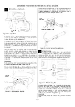
To calibrate the electronic Anti lag valve, the cap must be
removed to allow access to the manual override screw. Please
note that the valve seat must be in place before calibration.
Using an Allen key remove the 2 top bolts allowing the cap to be
removed, and a spacer or shift the cap off to one side and reinsert
at least one of the bolts. This prevents the preload in the
mechanism separating the housing potentially effecting the
calibration accuracy.
Figure 9
– Top Cap removed for calibration
Carefully move the motor wired allowing access to the manual
override below (Figure 12)
Figure 10
– Manual Override
Using a ¼” drive extension with a 5mm socket, turn the manual
override in a clockwise direction with your fingers until the
mechanism stops rotating. In this position the valve should be
home against the valve seat and will be your 0% position.
Remember to have the valve seat inserted.
CAUTION!
Do not apply excessive force to the manual override, doing
so will damage the product and effect the performance.
Figure 11
– ¼ Drive extension with 5mm socket manually
adjusting.
Using your ECU manager software, read the voltage from the
sensor and set this as your closed position.
Wind the manual adjustment in an anticlockwise direction until it
stops. From this position rotate the adjustment 2 full turns in a
clockwise direction. Read the sensor value and set this as 100%
valve travel.
Monitor sensor signal voltage to ensure no wrap around occurs
throughout the stroke of the valve that could affect operation.
CAUTION!
It is critical not to set the 100% position at the end of the
travel as this may lead to seizing of the anti-lag valve and
overloading the system.
NOTE!
Turbosmart recommends allowing additional clearance
from the end stops until the Anti lag valve control is tuned
to minimise risk of overshoot into end stops at high speeds.
Tuning
The anti-lag valve will come calibrated from Turbosmart,
the targeted values have been set with regards to the position
sensor are 0.5V (completely open) and 4.5V as (completely
closed), It’s important to note that as the anti-lag valve moves
through its range of motion that the valves are monitored to move
from 4.5V decreasing to 0.5V, 0% open to 100% open. This
should be done manually with the ECU package monitoring
Voltage Values. The electronic motor should be disconnected at
this point.
Voltage wraps around will cause errors with the Anti lag valve,
this is when the Voltage increases from 4.8V up to 5V and jumps
through to 0V.
Position Sensor
Target Voltage
Duty Cycle
100%
0.20-0.60V
~16%
0%
4.40-4.80V
~84%
It is important to set up the correct limits manually with anti-lag
valve. Turbosmart recommends that the valve is only ever
driven electronically to the maximum valve position of 90
%.
4
3
Cap retaining
bolts
Manual
Override
Valve Down
Valve UP
5


