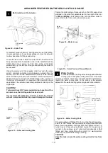
9
Driving the valve to 100% will cause increased wear on
components such as the electronic motor as it tries to
force the valve to completely open.
Adjust the calibration to allow plenty of overshoot to the end stops
of the valve, recalibrate as above once you have good control of
valve position.
PLEASE NOTE
that temperatures over 180 degC (356degF)
will create an error in the temperature sensor readings.
Therefore, the internal temperature is rated to a temperature of
150degC (302degF) it is recommended to log and place
sufficient alarms to monitor this.
PLEASE NOTE
When driving the electronic actuator, the current
should be limit to
no more
than 20 amps at a period of 1 second
and 5 amps for more than 5 seconds.
Follow your ECU manufacturers guidelines for tuning Anti lag
valve servo control. Ensure dead band is set to a reasonable
level to not have the output active when not needed.
Sensor Linearisation
Due to the nature of the poppet valve design, the flow
characteristics are nonlinear. In some cases, it may be
advantages to correlate the linear sensor output to match the flow
of the valve. The following plot compares valve position with
valve flow. A 3
rd
order polynomial is provided to relate sensor
position to flow. Note due to the design of the anti-lag valve, the
valve is on a preloaded mechanism to minimise binding at the
end stops, this results in the sensor reading past the home
positions and for this reason the calibration sequence with
low
force is essential.
y = 0.5596x
3
– 1.8306x
2
+ 2.2847x
– 0.0189
R
2
= 0.9989
Tuning Strategies
CAUTION!
- Tuning your antilag valve should be done by a professional
- Antilag valve is for race applications only
- The use of antilag creates excessive heat in the exhaust manifold and can shorten the life of turbo, exhaust manifold and related
systems
Activation and Shut Down
Criteria should be established within the ECU to control the
antilag valve, a minimum throttle percentage and delay to arm
the system with arming achieved when throttle is released with
an active time limit set.
It is a good idea to have limits set up to shut down the antilag
system if too much heat is being produced. Exhaust temperature
sensors and engine temp should be monitored and allowed to
deactivate the system if bordering dangerous levels.
Outputs should be set up to open the valve when enabled.
NOTE!
For best results, any bypass valves in the system should be
forced closed when in enabled to ensure compressor charge
is distributed into the exhaust manifold via the ALV.
Tuning
Each engine and set up will require different parameters to
achieve the desired results. Typically, a combination of ignition
retard, ignition cut, and fuel trim can be used to increase and
decrease the effectiveness of the system.
0.000
0.500
1.000
1.500
2.000
2.500
3.000
3.500
0
100
200
300
400
Sens
o
r
O
utp
ut
(V
)
Temperature
Deg C
Deg F
6
0%
50%
100%
150%
-20%
0%
20%
40%
60%
80%
100%
120%
-20%
0%
20%
40%
60%
80%
100%
120%
0%
50%
100%
150%
Sens
o
r
P
o
si
ti
o
n
V
al
ve
Fl
o
w
Valve lift
Sensor Linearisation
1
3
2
3


