6
GEN V ALV Accessories
TS-0550-3114
ALS 6-1 Weld flange
(for 6 cylinder/V12/6 outlet pipes)
TS-0550-3104
ALS 5-1 Weld flange
(for 5 cylinder/V10/5outlet pipes)
TS-0550-3098
ALS 4-1 Weld flange
(for 4 cylinder/V8/4 outlet pipes)
TS-0550-3099
ALS 3-1 Weld flange
(for 3 cylinder/V6/3 outlet pipes)
TS-0550-3100
ALS 2-1 Weld flange
(for 2 cylinder/2 outlet pipes)
TS-0505-3001
WG40 Inlet Weld Flange
(for single outlet)
TS-0550-3101
Inlet Weld Flange AL
TS-0550-3102
Inlet pipe adapter 1-3/4" OD
TS-0550-3103
Inlet pipe adapter 1-1/2" OD
TS-0552-3001
WG40 Valve Seat
TS-0552-3003
WG40 Inlet/WG45 Outlet V-Band
TS-0552-3004
WG40 Outlet V-Band
TS-0550-3076
WG40 weld purge bung
TS-0550-3080
V-Band Replacement Nut - 2 Pack
TS-0550-3009
WG38/40 Actuator Collar
FITTING YOUR GEN V ALV
Mounting your New Turbosmart Gen V ALV
(Anti Lag Valve)
The weld flanges should be welded to your exhaust system. The
weld flanges are compatible with stainless steel and mild steel
welding rod material.
For best results tubes should be plumbed into the turbo manifold
as close to the exhaust port of the engine for maximum efficiency.
Turbosmart Weld flanges are designed to accept 19mm (3/4”)
tube, large diameter tubes with the least amount of restriction will
achieve a higher amount of usable energy in the manifold.
CAUTION!
Do not place the actuator cap near a significant heat source
as this could shorten the life of the diaphragm.
CAUTION!
Use of the Antilag valve produces excessive heat in the
exhaust manifold and turbo and may result in shorter than
expected life.
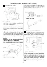
Plumbing the antilag valve into the exhaust port maximises the
thermal energy from the exhaust to increase the flame front with
fresh air and unburnt fuel.
Connect the inlet of the ALV to the charge intercooler piping pre-
throttle body, having the pipe, and attached at an angle in the
direction of flow may help the efficiency of the system.
Fitting the Gen V ALV
Prior to mounting the Gen V ALV, place v-band over weld on
flange by unscrewing the nut on the v-band as far out as possible
and then squeezing the bolt in a syringe motion to expand the v-
band (squeeze the dots together below). Once the v-band is in
its fully expanded position, slide the v-band over the flange to
allow for the ALV to be installed.
Do not forget to put the valve seat into the body before mounting
the unit on the exhaust manifold.
Using the 3/8” deep socket and
a torque wrench Tighten the V-Band to 7N.m (5 ft/lbs). Ensure
1
2
3
eALV
ALV
Runners
Turbo
Flange
Turbo pressure
source
ALV
Turbo
Turbo Compressor
housing
Figure 5
– ALV mounted on Exhaust Manifold
Figure 6
– ALV mounted on Turbo system


