Tritech International Ltd
Intelligent Gyro Compass
7.5
Electrical Installation
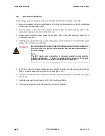
The following procedure should be followed to complete the Electrical Installation of the iGC:
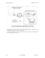
1. Make any necessary wiring and modifications to the Host control system to provide the appropriate
power supply and telemetry circuits.
2. With the power to the Host control system isolated, attach the interconnecting cable to the
appropriate underwater connector at the Host end.
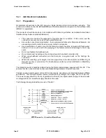
3. Using a digital multimeter, insert probes into sockets 1 and 2 of the interconnecting cable (prior to
connecting to the iGC).
4. Carefully power-up the Host supply (or the iGC supply circuit if switchable). Confirm that the output
voltage is the correct value and polarity.
Caution!
5. When the correct iGC supply voltage has been confirmed, isolate the iGC supply and check that
there is no power present on the connector sockets (pins 1 & 2).
6. Connect the female Subconn connector to the iGC, following the Subconn instructions in Section
7.4.1 above.
7. Carefully power-up the Host supply (or the iGC circuit if switchable).
8. Check correct operation of the iGC according to Section 10 below.
Issue 2
0707-SOM-00004
Page 21 of 51
Do not connect the cable to the iGC until provision of correct voltage to
the correct pins on the iGC connector has been checked (see Section 5 -
Commissioning).
Note:
The iGC input power connection is protected against reverse polarity
supply connections. If power is inadvertently connected in reverse
polarity, the iGC will not power up, but will not be damaged.
Содержание Intelligent Gyro Compass
Страница 13: ...Tritech International Ltd Intelligent Gyro Compass Issue 2 0707 SOM 00004 Page 14 of 51 ...
Страница 30: ...Tritech International Ltd Intelligent Gyro Compass Typical screenshot Issue 2 0707 SOM 00004 Page 31 of 51 ...
Страница 43: ...Tritech International Ltd Intelligent Gyro Compass Appendix F Parts List Issue 2 0707 SOM 00004 Page 44 of 51 ...

