Tritech International Ltd
Intelligent Gyro Compass
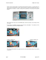
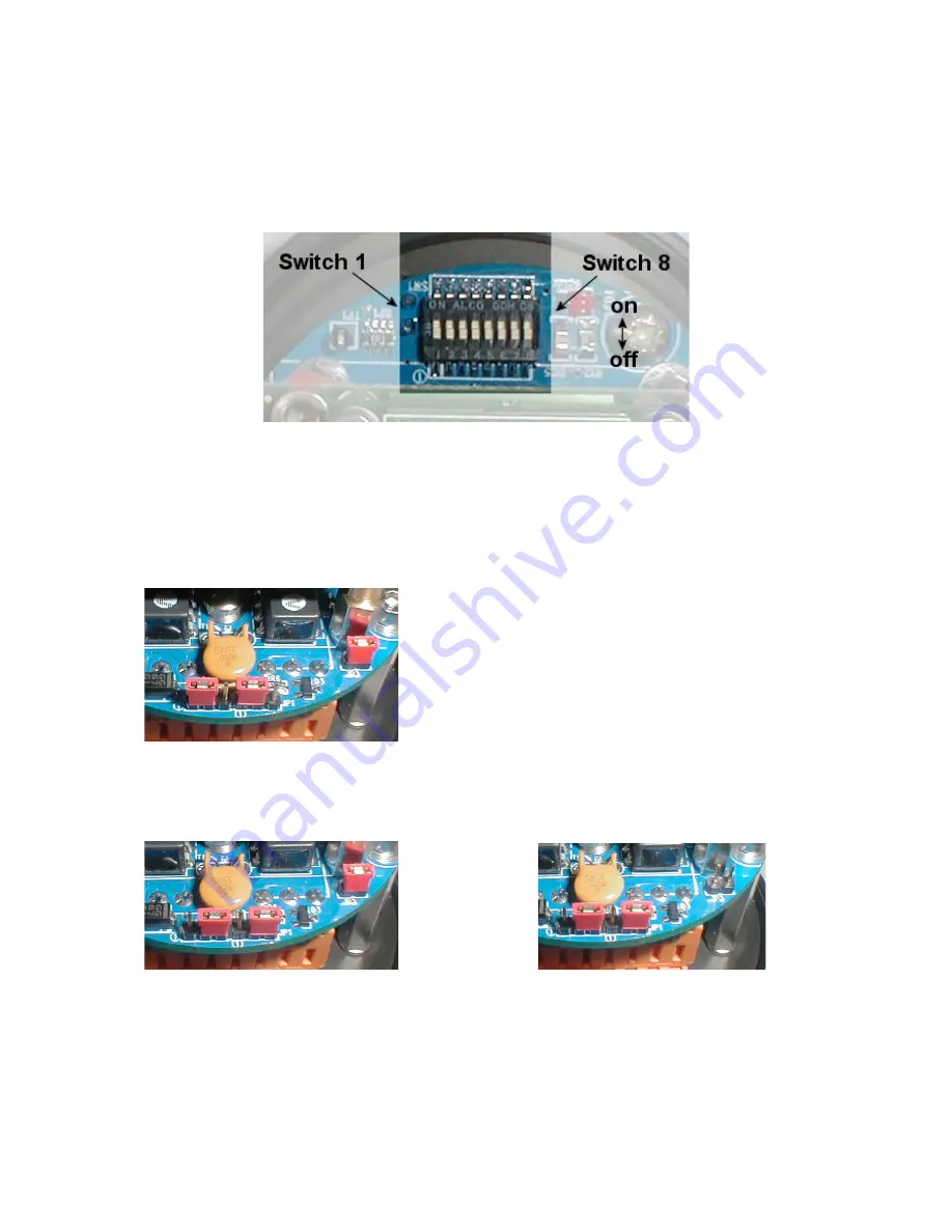
Set the DIL mode switch (SW1) to the desired setting (as determined above – and according to the
switch settings from Appendices C and D). Operate the switches carefully with a sliding motion using a
small jeweller’s screwdriver or similar, ensuring that the switches are moved fully into the desired
position.
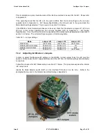
Once the DIL switch has been set, the RS485 jumpers should be checked / set according to Table
7.4.1 above.
The Jumpers are identified as small red shorting links (see photograph). The position to set the
Jumpers can be seen from the photographs below:
Settings for Arcnet mode:
Settings for RS485 mode
Settings for RS485 mode
terminated with 120R:
un-terminated:
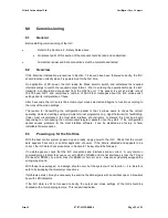
After setting the Mode Switch and Jumpers, the iGC can be re-assembled according to the procedure
in Section 8.7.
Issue 2
0707-SOM-00004
Page 20 of 51
Содержание Intelligent Gyro Compass
Страница 13: ...Tritech International Ltd Intelligent Gyro Compass Issue 2 0707 SOM 00004 Page 14 of 51 ...
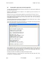
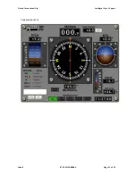
Страница 30: ...Tritech International Ltd Intelligent Gyro Compass Typical screenshot Issue 2 0707 SOM 00004 Page 31 of 51 ...
Страница 43: ...Tritech International Ltd Intelligent Gyro Compass Appendix F Parts List Issue 2 0707 SOM 00004 Page 44 of 51 ...

