


TMCM-1311 TMCL Firmware V1.11 Manual (Rev. 1.17 / 2015-NOV-05)
68
www.trinamic.com
Number Axis Parameter Description
Range [Unit]
Acc.
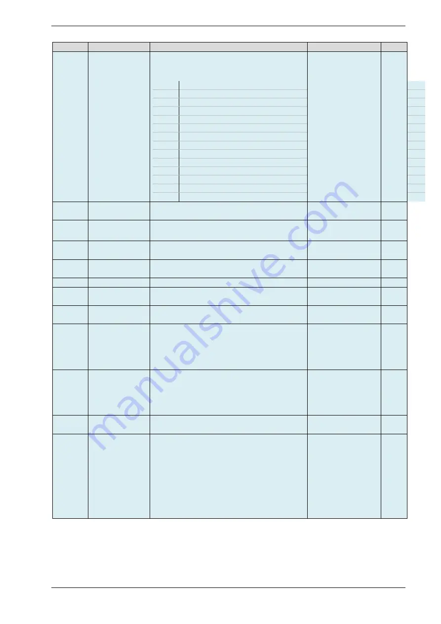
18
Status word
The status word contains 12 bits (bit 0… 11).
They can be read out using command GAP 18.
If a bit is set the specific event has occurred.
Bit 0
Target reached
Bit 1
Velocity reached
Bit 2
Closed loop mode
Bit 3
Position mode
Bit 4
Velocity mode
Bit 5
Torque mode
Bit 6
Home switch
Bit 7
Left stop switch
Bit 8
Right stop switch
Bit 9
Undervoltage
Bit 10 Overvoltage
Bit 11 Overtemperature
Bit 12 Position hold mode active
Bit 13 I
2
t value exceeded
0/1
R
19
CL torque mode
actual current
Actual current in torque mode
-3000… +3000
[mA]
R
20
CL torque mode
slope
Slope in torque mode (related to acceleration
and deceleration).
[mA/s]
RW
25
Thermal winding
time constant
Thermal winding time constant for the used
motor. Used for I²t monitoring.
0… +4294967295
[ms]
RWE
26
I²t limit
An actual I²t sum that exceeds this limit leads
to increasing the I²t exceed counter.
0… +4294967295
RWE
27
I²t sum
Actual sum of the I²t monitor.
0… +4294967295
R
28
I²t exceed
counter
Counts how often an I²t sum was higher than
the I²t limit.
0… +4294967295
RWE
29
Clear I²t
exceeded flag
Clear the flag that indicates that the I²t sum
has exceeded the I²t limit.
(ignored)
W
108
CL field
weakening
minimum
velocity
Minimum motor speed at which the speed
dependent Back EMF compensation will be
applied (field weakening).
Based on the velocity measured via encoder
feedback.
0… +327.679.999
[pps]
RW
109
CL field
weakening
maximum
velocity
Maximum motor speed for the speed
dependent Back EMF compensation will be
applied (field weakening).
Based on the velocity measured via encoder
feedback.
0… +327.679.999
[pps]
RW
112
CL encoder offset
Offset between encoder and electrical angle for
correction of possible misalignment.
[encoder steps]
Default = 0
RWE
113
CL current scale
minimum
Minimum current scale factor for current
regulation.
255 = 1 = 100% of maximum current
127 = 0.5 = 50% of maximum current
…
Attention!
The maximum current itself is defined by the
CS parameter of the motor driver chip (see axis
parameter 6)
Default = 15
[1/256]
RW