


TMCM-035 Manual (V2.09 / February 27
th
, 2009)
8/18
Copyright © 2007-2009, TRINAMIC Motion Control GmbH & Co. KG
4.1
Power Supply
The power supply for the TMCM-035 is 14V to 50V DC. The module is not protected against wrong
polarity. Also a +5VDC supply for module functionality is needed. Please use all listed pins for the
power supply inputs and ground parallel.
4.2
Motor Connection
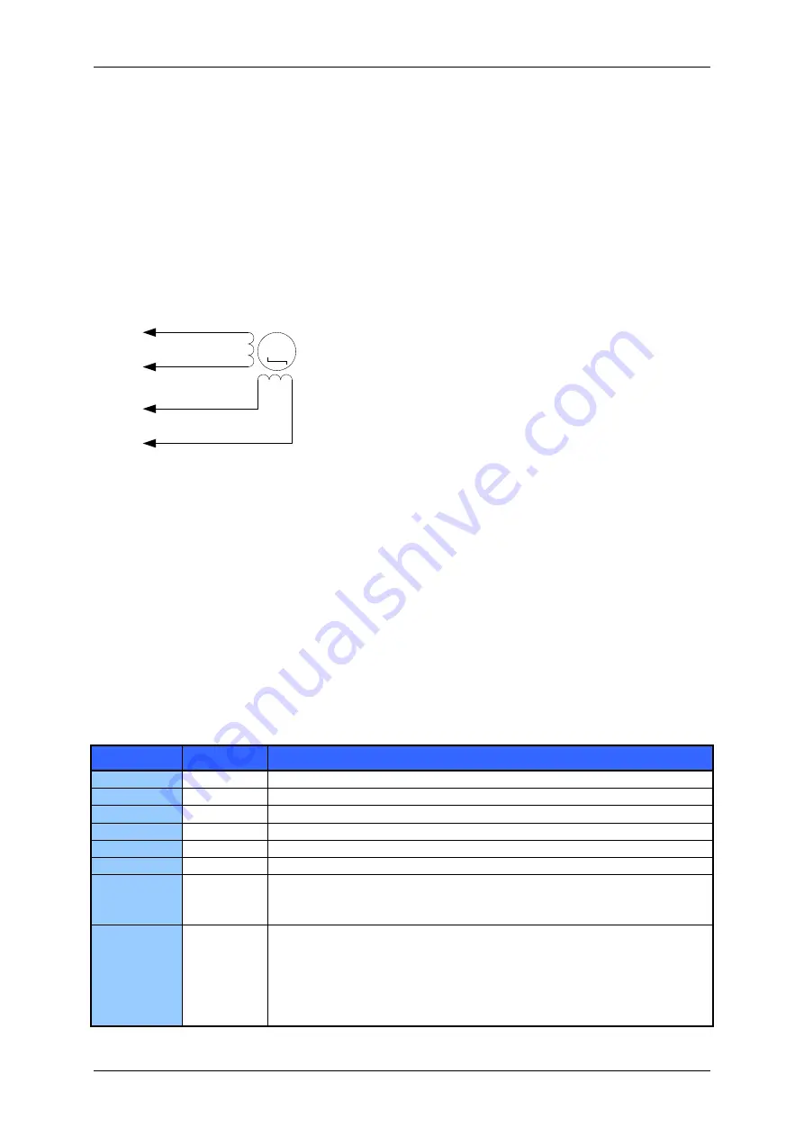
Connect the motor to the OA and OB pins. Always use all the pins to connect the motor! Connect one
coil of the motor to the OA1 (53, 54, 55, 56) and OA2 (49, 50, 51, 52) pins and the other coil to the
OB1 (41, 42, 43, 44) and OB2 (37, 38, 39, 40) pins.
Never connect or disconnect the motor while the
module is under power as this may damage the module.
M
OA1
OA2
OB1
OB2
Figure 4.2: How to connect the motor
4.3
Interfaces
The TMCM-035 has three different interfaces to fit in all applications. There is a SPI interface, a analog
interface and step / direction interface available. The classic analog interface provides very high
microstep resolutions but has compared to the SPI interface a disadvantage of poor diagnostics. SPI
on the other hand has all the diagnostics but is limited to 16x microstep resolution. Refer to 4.6.2 for
the possibility to increase microstep resolution to up to 64x for SPI.
4.3.1
SPI
The SPI interface pins of the connector are directly connected to the SPI pins of the TMC239. So, the
data that must be supplied via the SPI interface can be found in the TMC239 data sheet. The SPI data
can either be generated directly by a microcontroller or by a TMC428. To use the SPI interface you will
have to make the following connections:
Signal name Pin number Connection
SPE
19
High (can be left open, SPI enable)
SDEN
22
Connect to GND (to disable Step / Direction interface unit).
SDI
16
Connect to SPI bus
SDO
14
Connect to SPI bus
CSN
13
Connect to SPI bus
CLK
12
Connect to SPI bus
ANN
25
Set high (or leave open) for normal current settings or low to provide
the current reference via the INA and INB inputs (please see section
4.4.1 for details).
/STEP64EN
27
Leave open or connect to +5V to operate in 16 microstep mode, directly
using the 12 bits control shift register of the TMC239/249 (please refer to
the respective manuals)
Connect to GND for 64 microstep mode with 6 bit DAC. In this mode,
the SPI word is extended by an 8 bit shift register (see SPI table in
Figure 4.6).
Table 4.1: SPI interface connections


