background image

TMCM-035 Manual (V2.09 / February 27

th

, 2009) 


13/18 


Copyright © 2007-2009, TRINAMIC Motion Control GmbH & Co. KG 

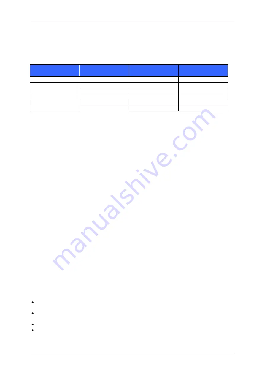
Another way of setting a different peak coil current is to connect the RSA pins to GND via an external 
resistor  and  the  RSB  pin  via  the  same  size  of  resistor.  The  two  resistors  should  be  in  the  range 
100mOhms  to  1  Ohm.  This  possibility  can  also  be  used  when  the  module  is  connected  via  its 
analogue interface. However it is very important to use SMD resistors with low inductivity and very 
short traces to GND for a stable operation in this configuration. 
 

peak coil current 

RMS current  
(microstep operation) 

RSA1, RSB1 

RSA2, RSB2 

1.0 A 

0.7 A 

open  

each 0.22 R to GND 

1.2 A 

0.85 A 

each 0.18R to GND  

open 

1.7 A 

1.2 A 

GND 

each 1.5R to GND 

2.1 A 

1.5 A 

GND 

each 0.47R to GND 

2.8 A 

2.0 A 

GND 

each 0.15R to GND 

4.2 A 

3.0 A 

each 0.27R to GND 

GND 

Table 4.8: Current fine adjustment with RSA and RSB 

4.4.2


Standby current reduction for Step-/ Direction mode 

In  step  /  direction  interface  mode,  the  current  control  will  switch  to  the  INA  and  INB  inputs  when 
there has been no step pulse for at least four seconds. Current control will switch back to the normal 
value set via RSA/RSB pins when the next step pulse occurs. This way the standby current can be set 
using  the  INA  and  INB  pins  (by  applying  a  voltage  between  0  (0%)  and  2V  (100%).  The  maximum 
current while the motor is running must be set using the RSA/RSB pins. 
The coil current should be reduced when the motor is standing still! 
 

Power down current set value = Value from Table 4.7 * (INA/INB-Voltage) / 2V 


4.4.3


Continuous Current restrictions / Thermal conditions 

The module is designed as a microstepping module, with sine wave currents (sine and cosine) driving 
both coils. The current peak of the sine wave can be as high as 5A, when the RMS current is set to 
3.5A. The mean motor current (RMS) is calculated by dividing the peak current by 1.41. 
 
The compact design of the module does not allow to continuously drive the full current unless forced 
air cooling is used to keep the board temperature below 85°C, because of excessive heat generation. 
On a short term basis, the board is allowed to reach 105°C, but it will shorten life time, if this occurs 
in longer periods. However, since continuous maximum current operation also shortens the lifetime of 
the  motor,  this  is  in  most  cases  no  restriction.  The  driver  transistors  on  the  module  (8  transistors 
labeled “4450” or similar) may heat up to 120°C at their surface - this is not critical! 
 
The  module  provides  a  thermal  protection,  but  this  is  only  meant  as  a  means  against  sudden 
destruction, i.e. when a cooling blower fails and the module slowly overheats. The protection is not 
meant to limit normal operation! It can not protect against all faults, since it is central in the TMC249 
IC, and might react too slowly! 
 

The following limits apply: 


Maximum  environment  temperature  for  up  to  3.5A  RMS  (= 

5A


peak

)  is 

40°C

,  module  mounted 

vertically 


Maximum environment temperature for up to 2.5A RMS (= 

3.5A


peak

) is 

60°C

, module mounted 

vertically 


If the module is mounted horizontally, use forced air flow for current above 2.0A RMS. 


The phase current should be reduced to a maximum of 70% of the above values while the motor 
is standing 

Содержание TMCM-035

Страница 1: ...t 2007 2009 TRINAMIC Motion Control GmbH Co KG TMCM 035 Manual 1 Axis stepper driver module 3 5A RMS 5A peak 50V Trinamic Motion Control GmbH Co KG Sternstra e 67 D 20357 Hamburg Germany http www trin...

Страница 2: ...ion Revision 18 7 References 18 List of Figures Figure 2 1 Dimensions 5 Figure 2 2 Pin order of the connector 5 Figure 4 1 Main parts of the TMCM 035 7 Figure 4 2 How to connect the motor 8 Figure 4 3...

Страница 3: ...via external inputs Since the new Version V2 0 of the board the module has been extended from maximum 16 to 32 and 64 microsteps Applications Driver module for a highly dynamic or high torque axis Ea...

Страница 4: ...equipment intended to support or sustain life and whose failure to perform when properly used in accordance with instructions provided can be reasonably expected to result in personal injury or death...

Страница 5: ...1 Figure 2 1 Dimensions The size of the module 80x50mm is the same as of the other Trinamic motion control modules It also uses the same connector The 68 pin connector has a 2 0mm pitch Bord outline...

Страница 6: ...ave open 18 In Step In 19 In SPE 0 Analog mode 1 SPI or Step Dir mode 20 In Dir In 21 In INA 22 In SDEN must be to 1 for Step Dir mode or 0 for SPI or Analog mode 23 In INB 24 In STEP16 Step Dir mode...

Страница 7: ...per motor ICOIL 1 4 ICOIL A fSTEP Step frequency 245 kHz tSPulse Step pulse length 0 1 s tS2D Direction hold time 2 s tD2S Direction to step delay 0 s VANA INx analog measurement range 0 3 V fSPI SPI...

Страница 8: ...er hand has all the diagnostics but is limited to 16x microstep resolution Refer to 4 6 2 for the possibility to increase microstep resolution to up to 64x for SPI 4 3 1 SPI The SPI interface pins of...

Страница 9: ...nly to be used to connect the TMCM 035 to a TMC453 chip or to a TMCM 100 module that contains a TMCM453 stepper motor controller chip The following pins are to be used in analogue mode Signal name Pin...

Страница 10: ...he LED shows the status of the module The LED is on when the motor is enabled and the supply voltage is high enough The LED is off when the motor is disabled due to pin 11 Enable set high or supply vo...

Страница 11: ...able 4 5 Step Direction interface connections Note Pins 12 13 14 16 and 25 must not be connected in this mode The Step Direction interface can also be used to connect the TMCM 035 module to a TMCM 100...

Страница 12: ...g inputs INA and INB In this case the ANN input pin 25 must be pulled low The INA and INB inputs supporting a voltage range of 0 to 3V can be used Use a simple voltage divider on the 5V supply to acco...

Страница 13: ...ue Value from Table 4 7 INA INB Voltage 2V 4 4 3 Continuous Current restrictions Thermal conditions The module is designed as a microstepping module with sine wave currents sine and cosine driving bot...

Страница 14: ...nce depends on the motor and mechanics For supply voltages above 24V and for low inductivity motors best microstep behavior is reached when mixed decay setting is continuously on Mixed decay should be...

Страница 15: ...6 CA3 15 CA2 14 PHB 19 MXA 7 CB1 6 CB0 5 CA1 4 CA0 3 2 1 0 Figure 4 6 SPI word assignment in 64 microstep mode Required TMC428 driver chain configuration for each TMCM 035 in 64 microstep mode 0x11 0x...

Страница 16: ...1 OUTA2 OUTB1 OUTB2 TMC249 TMC249 TMC249 3x TMCM 035 driver Figure 4 7 Application with 3 TMCM 035 controlled by a TMCM 301 The microstep configuration of the three TMCM 035 drivers digital pins 24 an...

Страница 17: ...to program the TMCM 301 with the following microstep table Figure 4 9 by pressing Set Please use the 64 microstep table to get the smoothest operation Figure 4 9 Microstep table for 64 microsteps in...

Страница 18: ...13 Feb 04 OK Ordering information added 2 00 20 Jun 06 BD 64 microstep version info added 2 01 14 Jul 06 HC Major revision 2 02 21 Aug 06 HC Additions to 64 microstep version info 2 03 29 Nov 06 BD Co...

Отзывы: