Chapter 19: Integration with Enterprise Equipment
TR0190 Rev. B1
120
19 Integration with Enterprise Equipment
The EL-500 supports authentication, accounting, and monitoring services that easily integrate
with enterprise equipment. In this section the following topics are described:
•
Splash pages
•
Layer 2 client emulation
Splash pages are not supported and Layer 2 emulation is unnecessary when
operating in bridge mode.
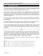
19.1 Configuring Splash Pages
The EL-500 supports splash pages, which can be used to restrict access to the 802.11
network and provide information to users that connect to the network. When a user connects
through a client access interface to an EL-500 with splash page support enabled, the splash
page for the appropriate interface will be displayed and the user will be restricted from
accessing other destinations on the Internet until they have logged in. The splash page can
require the user to enter logon credentials or simply click a button to complete the login
process.
To use splash pages, a number of URLs for login, successful login, and failed login must be
specified. A RADIUS server that provides authentication services may also need to be
specified.
19.1.1
Enabling Splash Pages
The enabling of splash pages can be controlled on a per-interface basis. Two splash page
modes are supported – one which requires client device users to login in to gain access to the
network and another which requires them to simply click on a button on the web page to
proceed.
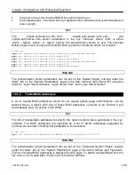
CLI
Enable or disable splash pages with the ‘splash.enable.wlan
N
’ parameters in the ‘sys’
interface. For a splash page to be displayed on an interface, the appropriate parameter must
be set to ‘yes’. The example below illustrates how to set the ‘splash.enable.wlan1’ parameter
in the ‘sys’ interface to enable splash pages for the wlan1 interface.
>
use sys
sys>
set splash.enable.wlan1=yes
BRIDGE
Содержание EL-500
Страница 20: ...Chapter 3 Using the Web Interface TR0190 Rev B1 20 Figure 8 Rebooting the EL 500...
Страница 33: ...Chapter 5 Initial Configuration of an ER 1000 TR0190 Rev B1 33 Figure 9 Initial configuration web page...
Страница 68: ...Chapter 11 Ethernet Interface Configuration TR0190 Rev B1 68 Figure 38 Wired DHCP settings...
Страница 108: ...Chapter 16 Controlling Access to the ER 1000 TR0190 Rev B1 108 Figure 50 VAP ACL configuration...


