Chapter 1: Working with the ER-1000
TR0190 Rev. B1
11
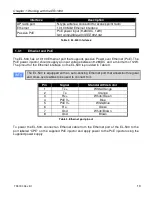
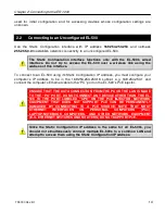
DO NOT CONNECT ANY DEVICE OTHER THAN THE EL-500 TO THE PORT
LABELED “CPE” ON THE PoE INJECTOR. NETWORK EQUIPMENT THAT
DOES NOT SUPPORT PoE CAN BE PERMANENTLY DAMAGED BY
CONNECTING TO A PoE SOURCE. NOTE THAT MOST ETHERNET
INTERFACES ON PERSONAL COMPUTERS (PCs), LAPTOP/NOTEBOOK
COMPUTERS, AND OTHER NETWORK EQUIPMENT (E.G. ETHERNET
SWITCHES AND ROUTERS) DO NOT SUPPORT PoE.
1.3.2
Antenna
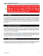
The EL-500 AP radio port is an N-type RF connector that can interface with a wide range of
Tranzeo antennas. After purchasing the desired 2.4GHz or 5.8GHz antenna (for the EL-500HG
or EL-500HA models respectively), attach the antenna to the access point (AP) radio port on
the EL-500. The antenna must be chosen such that its gain combined with the output power of
the radio complies with maximum radiation power regulatory requirements in the area the EL-
500 is used.
1.4
Deployment Considerations
The EL-500’s radio operates in either the 2.4 GHz or the 5.8 GHz ISM band, depending on the
model. It is possible that there will be other devices operating in these bands that will interfere
with the EL-500’s radio. Interference from adjacent EL-500s can also degrade performance if
the EL-500s are not configured properly.
It is advisable to carry out a site survey prior to installation to determine what devices are
operating in the band that your EL-500 uses. To detect the presence of other 802.11 devices,
a tool such as Netstumbler (
http://www.netstumbler.com/downloads/
) can be used. A spectrum
analyzer can be used for further characterization of interference in the band.
1.4.1
AP Channel Selection
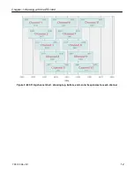
A site survey should be conducted to determine which access point channel will provide the
best performance. Some of the 802.11b/g channels that the EL-500HG’s radio can be
configured to use are overlapping. Only channels 1, 6, and 11 are non-overlapping.
Содержание EL-500
Страница 20: ...Chapter 3 Using the Web Interface TR0190 Rev B1 20 Figure 8 Rebooting the EL 500...
Страница 33: ...Chapter 5 Initial Configuration of an ER 1000 TR0190 Rev B1 33 Figure 9 Initial configuration web page...
Страница 68: ...Chapter 11 Ethernet Interface Configuration TR0190 Rev B1 68 Figure 38 Wired DHCP settings...
Страница 108: ...Chapter 16 Controlling Access to the ER 1000 TR0190 Rev B1 108 Figure 50 VAP ACL configuration...

