www.transvu.co.uk
Configuration & Operation Guide
9
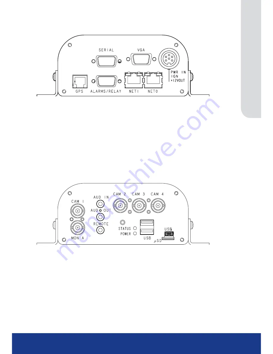
Front Panel
Description Function
SERIAL
RS232 port which defaults to the debug function
VGA
VGA output to allow connection of spot monitor (using this connection will
disable the MON A output)
PWR IN & IGN +12V OUT 12V fused input from battery
(refer to Connections)
&
12V output to support
ancillary equipment
(refer to Connections)
GPS
Standard RJ12 socket for connection to approved GPS unit
ALARMS/RELAY
9 way (female) D Type 24V 200mA
3 General Alarm Inputs/BS8414 EOL Alarms
1 Onboard light duty relay output (500mA@12V-48V Max)
NET1
RJ45 Ethernet network connector, 10/100 Mb/s Ethernet Network
NET0
RJ45 Ethernet network connector, 10/100 Mb/s Ethernet Network
Rear Panel
Description Function
CAM 1 - 4
75Ω BNC composite video inputs 1V pk-pk
MON A
75Ω BNC composite monitor output, 1V pk-pk
STEREO AUD IN
3.5mm phono socket, 8KHz/16KHz/22KHz sampling 75Ω input impedance, 1V
pk-pk
STEREO AUD OUT
3.5mm (phono) socket, line level <100Ω output impedance,1V pk-pk
amplification required
REMOTE
3.5mm socket for Remote IR extender (supplied)
STATUS LED
Illuminates red until the unit senses a failure condition
POWER LED
Illuminates red when the unit has power applied
USB
2x USB2.0 connectors
USB
1x Micro USB connector
μSD
Socket for micro SD storage card (minimum class 4)


