8
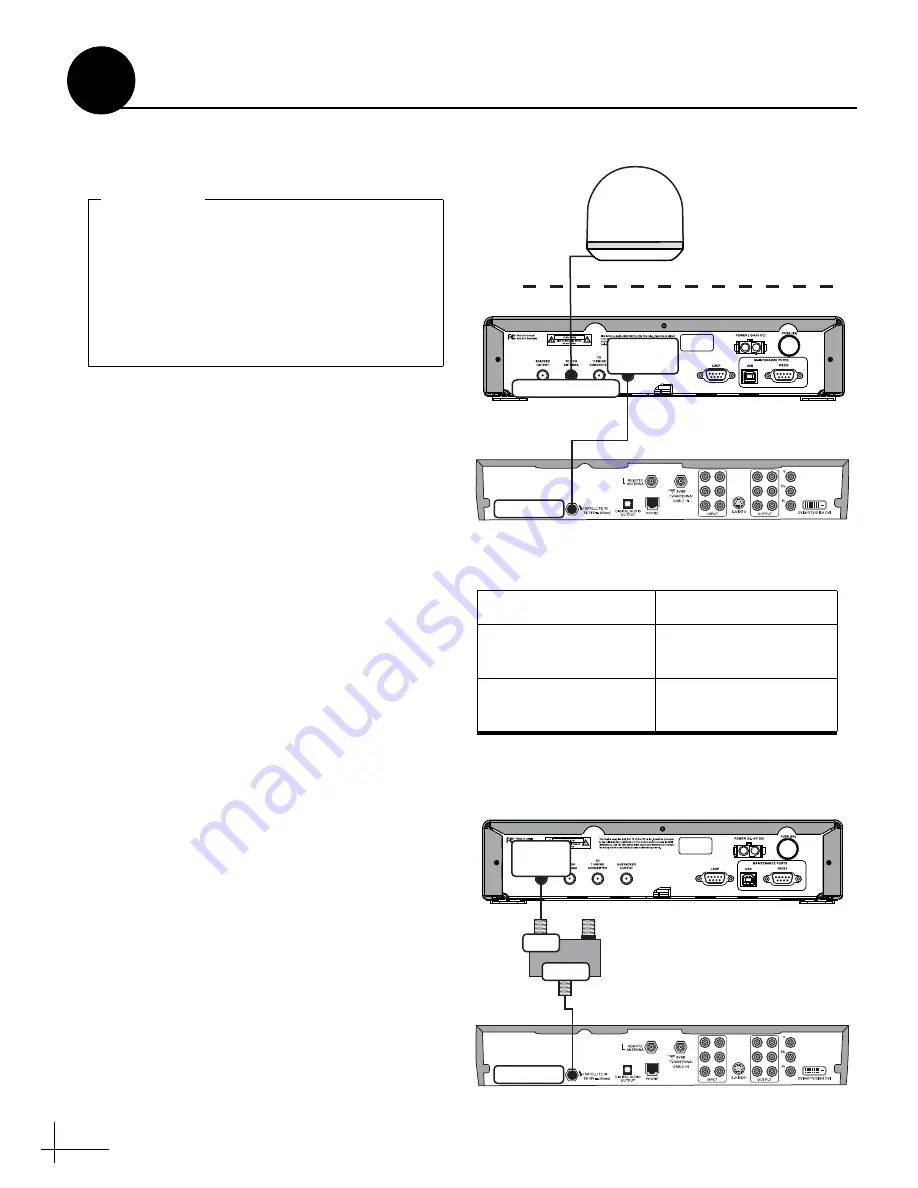
Follow these steps to connect the antenna cable
and receiver(s) to the interface box.
a.
Connect the antenna cable (A) to the “To
KVH Antenna” jack
on the interface box (see
b.
Connect an RF coaxial cable (B) from the
“Unstacked Output” jack on the interface box
to the “Satellite In” jack on the receiver. This
receiver will control satellite selection.
c.
Connect the receiver to the customer’s
television. Follow the instructions in the
receiver’s manual.
d.
If you need to connect an additional receiver,
connect the receiver to the “Stacked Output”
jack on the interface box through an in-line
destacker (see Figure 10 and Figure 11).
The destacker converts the stacked signal from the
interface box into an unstacked signal, which
receivers are configured to decode.
Terminate all RF coaxial cables, including the
antenna cable, with Snap-N-Seal
®
F-connectors using an Augat IT1000 tool.
Low-quality connectors will degrade system
performance and KVH’s warranty does not
cover repairs resulting from the use of such
connectors.
IMPORTANT!
(A)
(B)
S
atellite In
To KVH Antenna
Unstacked
O
u
tp
u
t
Roof
Interface Box
Primary
S
atellite TV Receiver
Antenna
Figure 9: Wiring the Interface Box
Figure 10: Destacker Models to Connect Additional Receiver(s)
# of Addl. Receivers
Destacker Model
1
Single-output
(KVH part #19-0347)
2
Dual-output
(KVH part #19-0410)
S
atellite In
S
tacked
O
u
tp
u
t
Interface Box
Additional
S
atellite TV Receiver
INPUT
To TV
OUTPUT / To RECEIVER
Destacker
Purchased Separately
(See table for model required)
Inp
u
t
O
u
tp
u
t
Figure 11: Connecting an Additional Receiver
Wire the Interface Box
6


