6
Follow these steps to connect the antenna cable to
the antenna.
a.
At the location you chose in Step 2 on page 4,
use a 5/8" hole saw to cut out a cable access
hole in the vehicle’s roof. Smooth the edges of
the hole to protect the cable.
b.
Route the RG6 antenna cable (the end with
the straight connector) down through the
cable access hole and into the vehicle. You
may remove the straight rubber boot for
easier cable routing. Later, you will connect
this end of the cable to the interface box.
c.
Connect the RG6 antenna cable (the end with
the right-angle connector and rubber sealing
boot) to the antenna. Hand-tighten, then
tighten with a 7/16" wrench for 1/4 turn to
ensure an electrical and weather-proof
d.
Position the rubber boot over the connector to
help protect the connector from the elements.
e.
Leave an adequate service loop,
approximately 8" of slack, in the antenna
cable for easy serviceability.
f.
Seal the cable access hole with a liberal
amount of silicone sealant (or equivalent) to
protect against leakage.
g.
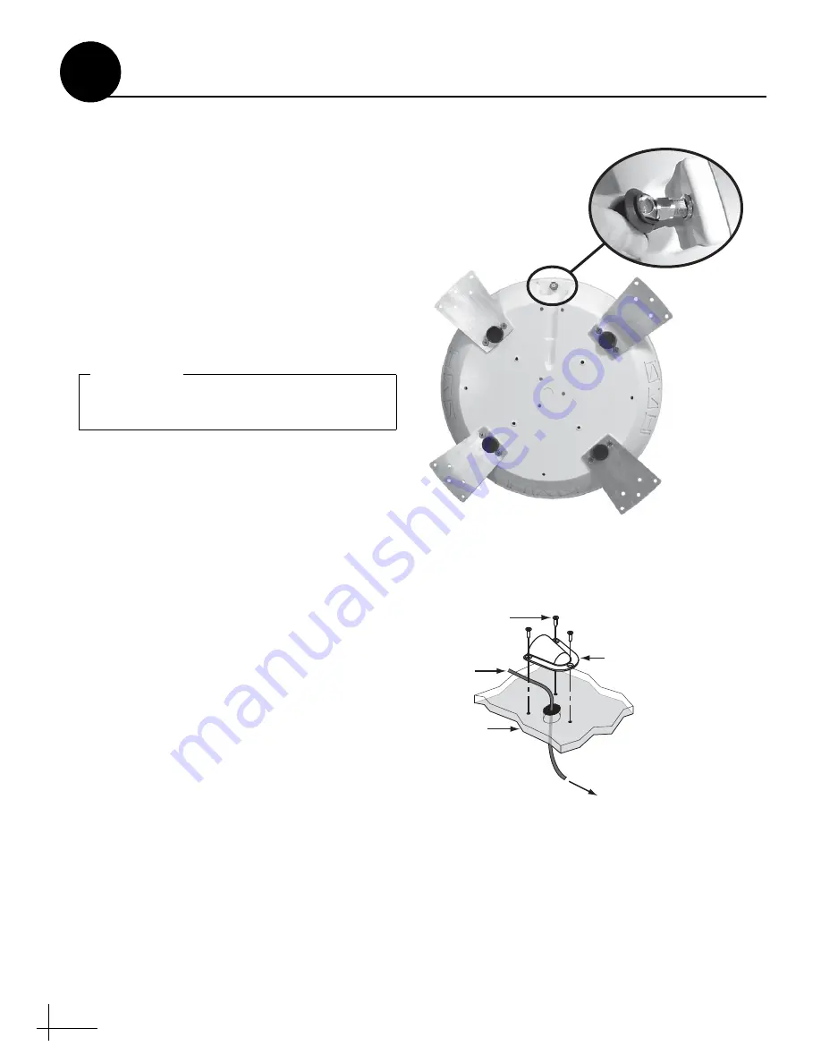
Install the supplied clamshell ventilator over
the cable access hole. The clamshell’s opening
should face the rear of the vehicle. Secure in
place with the three #6 screws supplied in the
kitpack (see Figure 7). Then seal the screws
with silicone sealant (or equivalent).
Do not kink the cable. Maintain a bend radius
of at least 3 inches.
IMPORTANT!
Figure 6: Connecting the Antenna Cable
#6 Screw (x3)
Cl
a
m
s
hell
Ventil
a
tor
Antenn
a
C
a
ble
Vehicle
Roof
To Interf
a
ce Box
Figure 7: Mounting the Clamshell Ventilator
Wire the Antenna
4


