background image


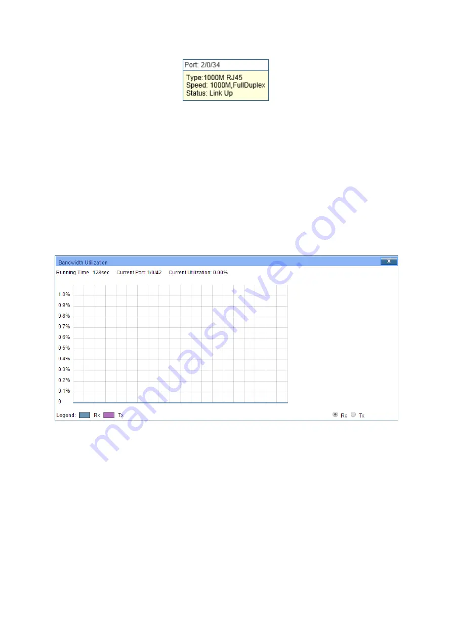
When the cursor moves on the port, the detailed information of the port will be displayed. 


Figure 4-2 Port Information 


Port Info 

Port: 

Displays the port number of the switch. 

Type: 

Displays the type of the port. 

Rate: 

Displays the maximum transmission rate of the port. 

Status: 

Displays the connection status of the port. 

Click a port to display the bandwidth utilization on this port. The actual rate divided by 
theoretical maximum rate is the bandwidth utilization. 

Figure 4-3

  displays the bandwidth 

utilization monitored every four seconds. Monitoring the bandwidth utilization on each port 
facilitates you to monitor the network traffic and analyze the network abnormities. 


Figure 4-3 Bandwidth Utilization 


Bandwidth Utilization 

Rx: 

Select Rx to display the bandwidth utilization of receiving 

packets on this port. 

Tx: 

Select Tx to display the bandwidth utilization of sending packets 

on this port. 

4.1.2 

Device Description 

On this page you can configure the description of the switch, including device name, device 
location and system contact. 
Choose the menu

 System→ System Info→ Device Description 

to load the following page.


16 

Содержание JetStream T3700G-52TQ

Страница 1: ...User Guide JetStream 52 Port Gigabit Stackable L3 Managed Switch T3700G 52TQ REV1 0 0 1910011776...

Страница 2: ...nt This equipment generates uses and can radiate radio frequency energy and if not installed and used in accordance with the instruction manual may cause harmful interference to radio communications O...

Страница 3: ...wer button the only way to completely shut off power is to disconnect the product or the power adapter from the power source Don t disassemble the product or make repairs yourself You run the risk of...

Страница 4: ...electrical and electronic equipment WEEE This means that this product must be handled pursuant to European directive 2012 19 EU in order to be recycled or dismantled to minimize its impact on the envi...

Страница 5: ...2 3 2 Configuration 12 Chapter 4 System 14 4 1 System Info 14 4 1 1 System Summary 14 4 1 2 Device Description 16 4 1 3 System Time 17 4 1 4 Daylight Saving Time 18 4 1 5 System IPv6 19 4 1 6 Manageme...

Страница 6: ...ample for Stack 52 Chapter 6 Switching 53 6 1 Port 53 6 1 1 Port Config 53 6 1 2 Port Mirror 54 6 1 3 Port Security 57 6 1 4 Protected Ports 58 6 1 5 Loopback Detection 59 6 1 6 Default Settings 62 6...

Страница 7: ...VPN 93 7 7 1 VLAN VPN Config 94 7 7 2 Default Settings 95 7 8 GVRP 95 7 8 1 GVRP Config 97 7 8 2 Default Settings 98 7 9 Private VLAN 98 7 9 1 PVLAN Config 100 7 9 2 Port Config 101 7 10 Application E...

Страница 8: ...fig 148 9 3 MVR 150 9 3 1 MVR Config 150 9 3 2 Interface Config 151 9 3 3 Member Config 153 9 3 4 Traffic 154 9 4 Multicast Table 155 9 4 1 Summary 155 9 4 2 Static Config 156 9 4 3 IGMP Snooping 158...

Страница 9: ...xy ARP 191 10 7 ARP 191 10 7 1 ARP Table 191 10 7 2 Static ARP 192 10 8 RIP 193 10 8 1 Basic Config 197 10 8 2 Interface Config 199 10 8 3 Application Example for RIP 200 10 9 OSPF 201 10 9 1 Process...

Страница 10: ...263 11 2 5 Application Example for IGMP 264 11 3 PIM DM 266 11 3 1 PIM DM Interface 271 11 3 2 PIM DM Neighbor 271 11 3 3 Application Example for PIM DM 273 11 4 PIM SM 274 11 4 1 PIM SM Interface 280...

Страница 11: ...3 1 Rate Limit 313 12 3 2 Storm Control 314 12 4 Voice VLAN 315 12 4 1 Global Config 316 12 4 2 Port Config 316 12 4 3 OUI Config 317 12 5 Auto VoIP 318 12 5 1 Auto VoIP Config 318 Chapter 13 ACL 321...

Страница 12: ...al Config 355 14 6 2 Port Config 355 14 7 AAA 358 14 7 1 RADIUS Server Config 359 14 7 2 TACACS Server Config 359 14 7 3 Authentication Method List Config 360 14 7 4 Application Authentication List Co...

Страница 13: ...LLDP MED 395 16 4 1 Global Config 395 16 4 2 Port Config 396 16 4 3 Local Info 398 16 4 4 Neighbor Info 399 Chapter 17 Maintenance 401 17 1 System Monitor 401 17 1 1 CPU Monitor 401 17 1 2 Memory Moni...

Страница 14: ...wo mounting brackets and other fittings Installation Guide Resource CD for T3700G 52TQ switch including This User Guide The Command Line Interface Guide SNMP Mibs 802 1X Client Software and its User G...

Страница 15: ...ormation and recommendations in this document do not constitute the warranty of any kind express or implied Users must take full responsibility for their application of any products In this Guide the...

Страница 16: ...escription system time and network parameters of the switch User Management Configure the user name and password for users to manage the switch with a certain access level System Tools Manage the conf...

Страница 17: ...resources of uplink devices and decrease broadcast Private VLAN mainly used in campus or enterprise networks to achieve user layer 2 separation and to save VLAN resources of uplink devices Chapter 8 S...

Страница 18: ...t Routing This module is used to configure several multicast routing protocols for multicast data forwarding Here mainly introduces Global Config IGMP Configure the IGMP features PIM DM Configure the...

Страница 19: ...o prevent the network from ARP attacks IP Source Guard Configure IP source guard feature to filter IP packets in the LAN DoS Defend Configure DoS defend feature to prevent DoS attack 802 1X Configure...

Страница 20: ...e system log function Device Diagnose Including Cable Test and Loopback Cable Test tests the connection status of the cable connected to the switch and Loopback tests if the port of the switch and the...

Страница 21: ...3700G 52TQ supports 2 power supply modules T3700G 52TQ can fully implement resilient scalable networks due to its advanced features such as OSPF VRRP IGMP and PIM DM SM 2 2 Appearance Description 2 2...

Страница 22: ...in the stack system Module On green An Interface Card is connected to the switch and works properly On yellow An Interface Card is connected to the switch but works improperly Off No Interface Card is...

Страница 23: ...card slot on the rear panel to install the expansion card TX432 of TP Link for example If TX432 is installed you get another two 10Gbps SFP ports Micro USB Console Port Designed to connect with the US...

Страница 24: ...switch has an RJ 45 console port and a micro USB console port available Console input is active on only one console port at a time By default the micro USB connector takes precedence over the RJ 45 c...

Страница 25: ...ame subnet addresses of the switch The IP address is 192 168 0 x x is any number from 2 to 254 Subnet Mask is 255 255 255 0 2 After a moment a login window will appear as shown in Figure 3 2 Enter adm...

Страница 26: ...tive before the switch is rebooted If you want to keep the configurations effective even the switch is rebooted please click Save Config You are suggested to click Save Config before cutting off the p...

Страница 27: ...mented on System Summary Device Description System Time Daylight Saving Time System IPv6 Management Port IPv4 and Management Port IPv6 pages 4 1 1 System Summary On this page you can view the port con...

Страница 28: ...es the 1000Mbps port is not connected to a device Indicates the 1000Mbps port is at the speed of 1000Mbps Indicates the 1000Mbps port is at the speed of 10Mbps or 100Mbps Indicates the SFP port is not...

Страница 29: ...Figure 4 3 displays the bandwidth utilization monitored every four seconds Monitoring the bandwidth utilization on each port facilitates you to monitor the network traffic and analyze the network abno...

Страница 30: ...running On this page you can configure the system time and the settings here will be used for other time based functions like ACL You can manually set the system time get UTC automatically if it has...

Страница 31: ...pecify the rate fetching time from NTP server Synchronize with PC S Clock When this option is selected the administrator PC s clock is utilized Note 1 The system time will be restored to the default w...

Страница 32: ...ation is one off in use Offset Specify the time adding in minutes when Daylight Saving Time comes Start End Time Select starting time and ending time of Daylight Saving Time Note When the DST is disab...

Страница 33: ...et IPv6 function You can set interface type as VLAN Port or Routed Port Link local Address Config Config Mode Select the link local address configuration mode Manual When this option is selected you s...

Страница 34: ...ddress from the DHCPv6 Server Add a Global Address Manually Address Format You can select the global address format according to your requirements EUI 64 Indicates that you only need to specify an add...

Страница 35: ...network Use this page to configure network information on the management port Choose the menu System System Info Management Port IPv4 to load the following page Figure 4 8 Management Port IPv4 The fo...

Страница 36: ...gement Port Configuration Protocol is None Gateway Specify the Gateway of the interface when the Management Port Configuration Protocol is None Status Displays interface current working status up or d...

Страница 37: ...refix and then the system will create a IPv6 address automatically Not EUI 64 Indicates that you have to specify an intact IPv6 address IPV6 Address When selecting the mode of EUI 64 please input the...

Страница 38: ...n The guest only can view the settings without the right to configure the switch the admin can configure all the functions of the switch The Web management pages contained in this guide are subject to...

Страница 39: ...Boot Config Config Restore Config Backup Firmware Upgrade System Reboot and System Reset pages 4 3 1 Boot Config On this page you can configure the boot file and the configuration file of the switch W...

Страница 40: ...the next startup image Backup Image Select the backup boot image Image Table Image Name The name of the image Flash Version The flash version of the image Software Version The software version of the...

Страница 41: ...ssfully the device will reboot to make the configuration change effective 4 Wrong uploaded configuration file may cause the switch unmanaged 4 3 3 Config Backup On this page you can download the curre...

Страница 42: ...Figure 4 15 Firmware Upgrade Note 1 Don t interrupt the upgrade 2 Upgrading the firmware will only upgrade the backup image 3 You are suggested to backup the configuration before upgrading 4 Please s...

Страница 43: ...urrent settings will be lost 4 4 Access Security Access Security provides different security measures for the remote login so as to enhance the configuration management security It can be implemented...

Страница 44: ...ble for configuration only when IP based mode is selected Only the users within the IP range you set here are allowed for managing the switch MAC Address The field can be available for configuration o...

Страница 45: ...ervices 1 Authenticate the users and the servers based on the certificates to ensure the data are transmitted to the correct users and servers 2 Encrypt the data transmission to prevent the data being...

Страница 46: ...g an IPv6 address for example 3001 1 for the switch you can log on to the switch s Web management page via https 3001 1 On this page you can configure the HTTPS function Choose the menu System Access...

Страница 47: ...Config Hard Timeout Configure hard timeout of HTTP sessions Soft Timeout Configure soft timeout of HTTP sessions Maximum Sessions Configure maximum allowable number of HTTP sessions Certificate and Ke...

Страница 48: ...werful authentication when you log on to the switch remotely through an insecure network environment It can encrypt all the transmission data and prevent the information in a remote management being l...

Страница 49: ...e supported protocol Protocol V2 Enable or disable SSH V2 to be the supported protocol Idle Timeout Specify the idle timeout time The system will automatically release the connection when the time is...

Страница 50: ...algorithm of SSH HMAC MD5 Select the checkbox to enable the HMAC MD5 algorithm of SSH Key Management You can get the status of the DSA and RSA keys which can also be generated or deleted here with the...

Страница 51: ...ample for SSH Network Requirements 1 Log on to the switch via password authentication using SSH and the SSH function is enabled on the switch 2 PuTTY client software is recommended Configuration Proce...

Страница 52: ...g to load the following page Figure 4 22 Access Control The following entries are displayed on this screen Global Config Telnet Enable or disable Telnet function globally on the switch 4 5 SDM Templat...

Страница 53: ...reboot Template Table SDM Template Displays the template name ARP Entries The maximum number of entries in the IPv4 Address Resolution Protocol ARP cache for routing interfaces IPv4 Unicast Routes The...

Страница 54: ...ack master to take charge of the operation management and maintenance of the stack while the other stack members process services and keep a copy configuration file in accordance with the master for p...

Страница 55: ...ure 5 2 Load Distribution and Backup across Devices 3 Network scalability Each member device in the stack system is able to process protocol packets and forward data individually which enables you to...

Страница 56: ...w Master Indicates the device is responsible for managing the entire stack system Member Indicates the device provides backup for the master If the master fails the stack will elect a new master from...

Страница 57: ...obably brings about routing and forwarding problems on the network since the partitioned stacks keep operating with the previous IP address by default which results in same IP address being reused in...

Страница 58: ...ect the complete topology information known as topology convergence Then the switch enters the master election stage 3 Master Election After all members have obtained topology information known as top...

Страница 59: ...herwise the unit number is configured based on the following rules and in the order listed 1 The device which was managed by the current master before the configuration will resume its unit number 2 T...

Страница 60: ...ce mainly functions to monitor the join and leave of member devices collect the new topology at any times and maintain the current topology When the stack is operating normally packets are transmitted...

Страница 61: ...Stack Info to load the following page Figure 5 7 Stack Info Configuration Procedure View the basic parameters of the stack function Entry Description Auto Copy Software Synchronization Displays the st...

Страница 62: ...ription of the switch Version Displays the current software version of the switch SFS Last Attempt Status Displays the status of the last stack firmware synchronization Up Time Displays the system up...

Страница 63: ...scription Role Config Master Set the switch as master Standby Member Set the switch as standby member Provision Info Unit ID Configure the switch number of the provisioned switch Device Type Configure...

Страница 64: ...tack Mode Configure the SFP port to be an Ethernet port or a stack port Running Stack Mode Displays whether the port is an Ethernet port or a stack port at the moment Link Status Displays the link sta...

Страница 65: ...Required On Stack Management Stack Config page configure the port s stack mode as Stack in Stack Port Config section 2 Configure unit ID Optional On Stack Management Stack Config page configure the u...

Страница 66: ...ection pages 6 1 1 Port Config On this page you can configure port status speed mode duplex mode flow control and jumbo frames for ports Choose the menu Switching Port Port Config to load the followin...

Страница 67: ...eed with the peer device thus avoiding the packet loss caused by congestion By default it is disabled Jumbo With this option properly configured the port can send jumbo frames The default MTU Maximum...

Страница 68: ...ing Port Port Mirror to load the following page Figure 6 2 Mirror Session List The above page displays a mirror session and no more session can be created Click Edit to configure the mirror session on...

Страница 69: ...d click Apply to make the settings effective Entry Description Session Displays session number Destination Port Input or select a physical port from the port panel as the mirroring port Ingress With t...

Страница 70: ...e learned on each port thus preventing the MAC address table from being exhausted by the attack packets Choose the menu Switching Port Port Security to load the following page Figure 6 4 Port Security...

Страница 71: ...Note 1 Port Security cannot be enabled on the member port of a LAG and the port with Port Security enabled cannot be added to a LAG 2 On one port Port Security and 802 1X cannot be enabled at the same...

Страница 72: ...up Protected ports in the same group cannot forward traffic to each other even if they are in the same VLAN But the protected ports can forward traffic to the unprotected ports and the ports that are...

Страница 73: ...tings effective 2 In the Port Config section select one or multiple ports for configuration Then set the parameters and click Apply to make the settings effective 3 View the loopback detection informa...

Страница 74: ...lay alerts It is the default setting Port based In addition to displaying alerts the switch will block the port on which the loop is detected Recovery Mode If you select Port Based as the operation mo...

Страница 75: ...resh Interval 6 seconds Port Status Disable Operation mode Alert Recovery mode Auto Return to CONTENTS 6 2 LAG With the LAG Link Aggregation Group function you can aggregate multiple physical ports in...

Страница 76: ...traffic evenly One LACP LAG supports more than eight member ports but at most eight of them can be active Using LACP protocol the switches negotiate parameters and determine the active ports When an a...

Страница 77: ...ng There are six options SRC MAC The computation is based on the source MAC addresses of the packets DST MAC The computation is based on the destination MAC addresses of the packets SRC MAC DST MAC Th...

Страница 78: ...ge you can manually configure the LAG The LACP feature is disabled for the member ports of the manually added Static LAG Choose the menu Switching LAG Static LAG to load the following page Figure 6 10...

Страница 79: ...to avoid data stream transferring only on one physical link For example if the destination device of the packets is a server with the fixed MAC address and IP address you can set the algorithm as SRC...

Страница 80: ...d value ranges from 1 to 64 Port Priority Specify the Port Priority A smaller value means a higher port priority The port with higher priority in an LAG will be selected as the active port to forward...

Страница 81: ...the traffic and analyze the network abnormity Choose the menu Switching Traffic Monitor Traffic Summary to load the following page Figure 6 12 Traffic Summary Configuration Procedure 1 To get the real...

Страница 82: ...eceived on the port Error octets are counted in Octets Tx Displays the number of octets transmitted on the port Statistics Click the Statistics button to view the detailed traffic statistics of the po...

Страница 83: ...nted in Unicast Displays the number of good unicast packets received or sent on the port Error frames are not counted in Jumbo Displays the number of jumbo frames received or sent on the port Alignmen...

Страница 84: ...t packets and enhance the efficiency of packets forwarding remarkably The address filtering feature allows the switch to filter the undesired packets and forbid its forwarding so as to improve the net...

Страница 85: ...pe of your desired entry All This option allows the address table to display all the address entries Static This option allows the address table to display the static address entries only Dynamic This...

Страница 86: ...tworks the static MAC address entries can facilitate the switch to reduce broadcast packets and remarkably enhance the efficiency of packets forwarding without learning the address The static MAC addr...

Страница 87: ...1 If the corresponding port number of the MAC address is not correct or the connected port or the device has been changed the switch cannot forward the packets correctly Please reset the static addres...

Страница 88: ...he pull down list and click the Search button to find your desired entry in the Dynamic Address Table MAC Enter the MAC address of your desired entry VLAN ID Enter the VLAN ID number of your desired e...

Страница 89: ...short the switch may remove valid MAC address entries This decreases the forwarding performance of the switch It is recommended to keep the default value 6 4 4 Filtering Address The filtering address...

Страница 90: ...corresponding filtering address It is multi optional MAC Address Displays the filtering MAC Address VLAN ID Displays the corresponding VLAN ID Port Here the symbol __ indicates no specified port Type...

Страница 91: ...wn Hosts in the same VLAN communicate with one another as if they are in a LAN However hosts in different VLANs cannot communicate with one another directly Therefore broadcast packets are limited in...

Страница 92: ...ation MAC address and source MAC address to show the information about VLAN As shown in the following figure a VLAN tag contains four fields including TPID Tag Protocol Identifier Priority CFI Canonic...

Страница 93: ...ting VLANs the PVID of each port indicating the default VLAN to which the port belongs is an important parameter with the following two purposes 1 When the switch receives an un VLAN tagged packet it...

Страница 94: ...o load the following page Figure 7 3 VLAN Table To ensure the normal communication of the factory switch the default VLAN of all ports is set to VLAN1 The following entries are displayed on this scree...

Страница 95: ...e untagged port which is ACCESS TRUNK or GENERAL UNIT Select the unit ID of the desired member in the stack Tagged port Displays the tagged port which is TRUNK or GENERAL 7 1 2 Port Config Before crea...

Страница 96: ...rt is UNTAG The PVID is same as the current VLAN ID If the current VLAN is deleted the PVID will be set to 1 by default TRUNK The TRUNK port can be added in multiple VLANs The egress rule of the port...

Страница 97: ...2 1Q VLAN Port Config page set the link type for the port basing on its connected device 2 Create VLAN Required On the VLAN 802 1Q VLAN VLAN Config page click the Create button to create a VLAN Enter...

Страница 98: ...ts VLAN ID as 10 owning Port 2 and Port 3 3 Create VLAN20 Required On VLAN 802 1Q VLAN VLAN Config page create a VLAN with its VLAN ID as 20 owning Port 3 and Port 4 Configure switch B Step Operation...

Страница 99: ...ived port Thus the packet is assigned automatically to the corresponding VLAN for transmission 2 When receiving tagged packet the switch will process it basing on the 802 1Q VLAN If the received port...

Страница 100: ...ok A is 00 19 56 8A 4C 71 Notebook B s MAC address is 00 19 56 82 3B 70 Network Diagram Configuration Procedure Configure switch A Step Operation Description 1 Configure the Link Type of the ports Req...

Страница 101: ...A 4C 71 5 Configure MAC VLAN 20 On VLAN MAC VLAN MAC VLAN page create MAC VLAN10 with the MAC address as 00 19 56 82 3B 70 Configure switch C Step Operation Description 1 Configure the Link Type of th...

Страница 102: ...hus the packet is assigned automatically to the corresponding VLAN for transmission 2 When receiving tagged packet the switch will process it basing on the 802 1Q VLAN If the received port is the memb...

Страница 103: ...the following page Figure 7 10 Configure Protocol Group Configuration Procedure 1 Specify a Template ID and a VLAN ID 2 Add your desired ports into this protocol group 3 Click Apply to make the settin...

Страница 104: ...template ID for the protocol template Protocol Name Give a name for the protocol template Ether Type Enter the Ethernet protocol type field in the protocol template Note The Protocol Template bound t...

Страница 105: ...e egress rule of Port 12 as Untag 3 Create VLAN20 Required On VLAN 802 1Q VLAN VLAN Config page create a VLAN with its VLAN ID as 20 owning Port 11 and Port 12 and configure the egress rule of Port 12...

Страница 106: ...network access terminal of the Internet Service Provider And these packets will be transmitted with double tag across the public networks The VLAN VPN function provides you with the following benefits...

Страница 107: ...of Ethernet frame protocol type in common use This VLAN VPN function is implemented on the VPN Config VLAN Mapping and Port Enable pages 7 7 1 VLAN VPN Config On this page you can configure the VLAN V...

Страница 108: ...n receiving the Join message from the other entity or configuring some attributes statically the device also sends out a Join message in order to be registered by the other GARP entities Leave Message...

Страница 109: ...ation on this entity After that the entity restarts the LeaveAll timer to begin a new cycle GVRP GVRP as an implementation of GARP maintains dynamic VLAN registration information and propagates the in...

Страница 110: ...address and a VLAN ID Then click Create to make the settings effective 1 Globally enable the GVRP feautre 2 Configure the parameters for ports 3 Click Apply to make the settings effective Entry Descr...

Страница 111: ...t receive a Join message again before the timer times out The Leave Timer ranges from 20 to 600 centiseconds LAG Displays the LAG to which the port belongs Note LeaveAll Timer 10 Leave Timer Leave Tim...

Страница 112: ...st port is the same as the Secondary VLAN ID One host port can only belong to one Private VLAN Primary VLAN A Private VLAN has one Primary VLAN and one Secondary VLAN Primary VLAN is the user VLAN upl...

Страница 113: ...ted on the PVLAN Config and Port Config pages 7 9 1 PVLAN Config On this page you can create Private VLAN and view the information of the current defined Private VLANs Choose the menu VLAN Private VLA...

Страница 114: ...VLAN 7 9 2 Port Config The Private VLAN provides two Port Types for the ports Promiscuous and Host Usually the Promiscuous port is used to connect to uplink devices while the Host port is used to conn...

Страница 115: ...ription 1 Create Private VLAN Required On the VLAN Private VLAN PVLAN Config page enter the Primary VLAN and Secondary VLAN select one type of secondary VLAN and then click the Create button 2 Add por...

Страница 116: ...ondary VLAN and then click the Create button 2 Add Promiscuous port to Private VLANs Required On the VLAN Private VLAN Port Config page configure the port type of Port 1 0 2 and Port 1 0 4 as Promiscu...

Страница 117: ...he VLAN Private VLAN Port Config page configure the port type of Port 1 0 3 as Promiscuous enter Primary VLAN 6 and Secondary VLAN 5 and click the Apply button 3 Add Host port to Private VLANs Require...

Страница 118: ...ue will be elected as the root bridge If the priority of all the switches are the same the switch with the lowest MAC address is selected as the root bridge Root Bridge The root of a spanning tree The...

Страница 119: ...is the root port of switch B and port 5 is the root port of switch C port 1 and 2 are the designated ports of switch A and port 4 is the designated port of switch B port 6 is the blocked port of switc...

Страница 120: ...s Step Operation 1 If the priority of the BPDU received on the port is lower than that of the BPDU of the port itself the switch discards the BPDU and does not change the BPDU of the port itself If th...

Страница 121: ...port once the old root port failed The backup port can rapidly transit to the new designated port once the old designated port failed The condition for the designated port to transit its port state r...

Страница 122: ...al Spanning Tree A special MST instance with an instance ID of 0 By default all the VLANs are mapped to IST CST Common Spanning Tree A CST is the spanning tree in a switched network that connects all...

Страница 123: ...If a port is not selected as the designated port for it receives better BPDUs from another switch it will become an alternate port In RSTP MSTP the alternate port is the backup for the root port It i...

Страница 124: ...d parameters Choose the menu Spanning Tree STP Config STP Config to load the following page Figure 8 4 STP Config Configuration Procedure 1 Enable spanning tree function select the STP mode and click...

Страница 125: ...lue is 5 Max Hops Specify the maximum number of hops that occur in a specific region before the BPDU is discarded The valid values are from 1 to 40 and the default value is 20 Max Hops is a parameter...

Страница 126: ...w the related parameters for Spanning Tree function Choose the menu Spanning Tree STP Config STP Summary to load the following page Figure 8 5 STP Summary 8 2 Port Config On this page you can configur...

Страница 127: ...by 16 and the default value is 128 The port with the lower value has the higher priority In the same condition the port with the highest priority will be elected as the root port in CIST Ext Path Cos...

Страница 128: ...t they can transit their states to forwarding directly Three options are supported Auto Open Force and Close Force By default it is Auto Auto The switch automatically detects if the port is connected...

Страница 129: ...onnected The port is enabled with spanning tree function but not connected to any device LAG Displays the LAG number which the port belongs to Note 1 Configure the ports connected directly to terminal...

Страница 130: ...ion using up to 32 characters By default it is the MAC address of the switch Revision Enter the revision from 0 to 65535 for MST region identification By default it is 0 8 3 2 Instance Config Instance...

Страница 131: ...s the higher priority and the switch with the highest priority will be elected as the root bridge in the desired instance VLAN ID Enter the VLAN ID mapped to the corresponding instance ID After the mo...

Страница 132: ...tance ID for its port configuration 2 Configure port parameters in the desired instance Instance ID Select Instance ID Select the desired instance ID for its port configuration Instance Port Config UN...

Страница 133: ...a backup of a root port Backup Port Indicates the port is a backup of a designated port Disabled Indicates the port is not participating in the spanning tree Port Status Displays the port status Forw...

Страница 134: ...ommended to enable this function on root ports and alternate ports If the switch cannot receive BPDUs because of link congestions or link failures the root port will become a designated port and the a...

Страница 135: ...otect function enabled the edge port will be shut down when it receives BPDUs and reports these cases to the administrator Only the administrator can restore it BPDU Filter BPDU filter function is to...

Страница 136: ...nfiguration It is multi optional Port Displays the port number of the switch Loop Protect Enable or disable the Loop Protect function It is recommended to enable this function on root ports and altern...

Страница 137: ...enabled the edge port will be shut down when it receives BPDUs and reports these cases to the administrator Only the administrator can restore it BPDU Filter Enable or disable the BPDU Filter function...

Страница 138: ...or the port 3 Configure the region name and the revision of MST region On Spanning Tree MSTP Instance Region Config page configure the region as TP Link and keep the default revision setting 4 Configu...

Страница 139: ...switch B as the designated bridge of Instance 2 On Spanning Tree MSTP Instance Instance Config page configure the priority of Instance 2 to be 4096 Configure Switch C Step Operation Description 1 Con...

Страница 140: ...ig page enable STP function and select MSTP version On Spanning Tree Port Config Port Config page enable MSTP function for the port 3 Configure the region name and the revision of MST region On Spanni...

Страница 141: ...ggestion for Configuration Enable TC Protect function for all the ports of switches Enable Root Protect function for all the ports of root bridges Enable Loop Protect function for the non edge ports E...

Страница 142: ...ppose a point to multi point service is required unicast is suitable for networks with sparsely users whereas broadcast is suitable for networks with densely distributed users When the number of users...

Страница 143: ...dress a logical MAC address is needed to be used as the destination address As stipulated by IANA the high order 24 bits of a multicast MAC address begins with 01 00 5E while the low order 23 bits of...

Страница 144: ...es transmitted between the host and the router and tracks the IGMP messages and the registered port When receiving IGMP report message the switch adds the port to the multicast address table when the...

Страница 145: ...le when its member port time times out The host running IGMPv2 or IGMPv3 sends IGMP leave message when leaving a multicast group to inform the multicast router of its leaving When receiving IGMP leave...

Страница 146: ...re displayed on this screen Global Config IGMP Snooping Enable or disable IGMP Snooping function globally on the switch Unknown Multicast Configure the way how the switch processes the multicast data...

Страница 147: ...for the desired port If Fast Leave is enabled for a port the switch will immediately remove this port from the multicast group upon receiving IGMP leave messages Member Port Time Member ports are port...

Страница 148: ...o Note 1 Fast Leave on the port is effective only when the host supports IGMPv2 or IGMPv3 2 When both Fast Leave feature and Unknown Multicast Discard feature are enabled the leaving of a user connect...

Страница 149: ...switch doesn t receive IGMP query message from the router port it will consider this port is not a router port any more Max Response Time Enter the host s maximum response time to general query messag...

Страница 150: ...ping is not enabled in the VLAN thus the multicast data in the VLAN will be broadcasted 9 1 4 Querier Config In an IP multicast network that runs IGMP a Layer 3 multicast device works as an IGMP queri...

Страница 151: ...ry Interval which is amount of time the device remains in non querier mode after it has discovered that there is a multicast querier in the network IGMP Snooping Querier Table Select Select the desire...

Страница 152: ...he profile Permit Only permit the IP address within the IP range and deny others Deny Only deny the IP address within the IP range and permit others Search Option Profile ID Enter the profile ID the d...

Страница 153: ...dress within the IP range and deny others Deny Only deny the IP address within the IP range and permit others Add IP range Start IP Enter the start IP address of the IP range End IP Enter the end IP a...

Страница 154: ...ends MLD query messages After receiving the MLD query messages the switch will remove the port from the multicast address table if the switch receives no MLD report message from the host within a peri...

Страница 155: ...ly reset 3 Member Leave The host will send MLD Done message when leaving a multicast group to inform the router of its leaving When Immediate Leave is not enabled in a VLAN and a Done message is recei...

Страница 156: ...unknown multicast data Unknown IPv6 multicast packets refer to those packets without corresponding forwarding entries in the IPv6 multicast table When unknown multicast filter is enabled the switch w...

Страница 157: ...Leave is enabled for a port the switch will immediately remove this port from the multicast group upon receiving MLD done messages Member Port Time Member ports are ports connected to multicast group...

Страница 158: ...he LAG number 9 2 3 VLAN Config Multicast groups established by MLD Snooping are based on VLANs On this page you can configure different MLD parameters for different VLANs Choose the menu Multicast ML...

Страница 159: ...ure of the VLAN Member Port Time Displays the member port time of the VLAN Router Port Time Displays the router port time of the VLAN Max Response Time Displays the max response time of the VLAN Stati...

Страница 160: ...ant to receive IP multicast traffic The MLD snooping feature listens to these MLD reports to establish appropriate forwarding Query VLAN Address Enter the General Query Message source IP address MLD V...

Страница 161: ...ime Last Querier Address Table VLAN ID Displays the VLAN ID Last Querier Address Displays the Last Querier Address MLD Version Displays the Last Querier Version 9 2 5 Profile Config On this page you c...

Страница 162: ...s the profile ID Mode Displays the attribute of the profile Permit Only permit the IP address within the IP range and deny others Deny Only deny the IP address within the IP range and permit others Bi...

Страница 163: ...ent VLANs In IGMP snooping if member ports are in different VLANs a copy of the multicast streams is sent to each VLAN that has member ports While MVR provides a dedicated multicast VLAN to forward mu...

Страница 164: ...on the Multicast VLAN Multicast VLAN Specify the VLAN on which the multicast data will be received Query Response Time Set the maximum time wait for the IGMP membership report on a receiver port When...

Страница 165: ...ure MVR settings on the specific interface It is multi optional Port Displays the port number of the switch Mode Enable or disable MVR on this port Type Configure an port as one of the following type...

Страница 166: ...leave message is received on this port without sending an IGMP query message and waiting for the IGMP group membership report This function should only be enabled on receiver ports to which a single...

Страница 167: ...t VLAN and the IP multicast address specified above Multicast VLAN Registration Group Table MVR Group IP Displays the IP multicast address Status Displays the status of the multicast group Members Dis...

Страница 168: ...following page Figure 9 20 Multicast Table The following entries are displayed on this screen Multicast MAC Address Stats Max MFDB Table Entries Displays the Max MFDB Table Entries Most MFDB Entries...

Страница 169: ...multicast MAC entries Source Displays the source of the multicast MAC entries Type Displays the type of the multicast MAC entries Forward Port Displays the forward port of the multicast MAC entries 9...

Страница 170: ...All Displays all multicast MAC entries VLAN ID Enter the VLAN ID the desired entry must carry MAC Address Enter the multicast MAC address the desired entry must carry Forward Port Enter the forward po...

Страница 171: ...d the desired entries quickly All Displays all multicast MAC entries VLAN ID Enter the VLAN ID the desired entry must carry MAC Address Enter the multicast MAC address the desired entry must carry For...

Страница 172: ...address the desired entry must carry Forward Port Enter the forward port number the desired entry must carry MLD Multicast MAC Address Table VLAN ID Displays the VLAN ID of the multicast MAC entries M...

Страница 173: ...Address List Enter the source address list the desired entry must carry Source Specific Multicast Groups Table VLAN ID Displays the VLAN ID of the entries Group Displays the Group of the entries Inter...

Страница 174: ...de Enter the source filter mode the desired entry must carry Interface Enter the interface the desired entry must carry Source Specific Multicast Groups Table VLAN ID Displays the VLAN ID of the entri...

Страница 175: ...s Ever Used of source specific multicast Current Entries Displays the Current Entries of source specific multicast MLD Snooping Total Entries Displays the Max MFDB Table Entries Most SSM FDB Entries E...

Страница 176: ...interface in Layer 3 mode and mainly used for realizing the Layer 3 connectivity between VLANs or routed ports Each VLAN interface is corresponding to one VLAN Each routed port is corresponding to on...

Страница 177: ...the ID of the interface Mode Displays IP address allocation mode None without ip Static setup manually DHCP allocated through DHCP IP Address Displays the IP address of the interface Subnet Mask Displ...

Страница 178: ...erface ID Displays ID of the interface including VLAN ID loopback interface and routed port IP Address Mode View and modify the IP address allocation mode None without ip Static setup manually DHCP al...

Страница 179: ...his page displays the routing information summary generated by different routing protocols Choose the menu Routing Routing Table Routing Table to load the following page Figure 10 4 Routing Table Rout...

Страница 180: ...s to add a static route Then click Create 2 In the Static Route Table section you can view the corresponding interface entry you create Entry Description Static Routing Config Static Route Table Desti...

Страница 181: ...2 168 0 1 the mask as 255 255 255 0 and the interface name as VLAN10 Destination Address Displays the destination IP address of the packets Subnet Mask Displays the subnet mask of the destination IP a...

Страница 182: ...outing Static Routing Static Routing Config add a static route entry with the destination as 192 168 0 0 the subnet mask as 255 255 255 0 and the next hop as 192 168 1 1 Configure the PCs Configure th...

Страница 183: ...ation parameters are manually specified by the administrator and are assigned to these clients via a DHCP server 2 Automatic Assignment The DHCP server must supplies the configuration parameters to DH...

Страница 184: ...d 4 DHCP acknowledgement The server selected in the DHCP REQUEST message commits the binding for the client to persistent storage and responds with a DHCP ACK message containing the configuration para...

Страница 185: ...ore its protocol software has been configured should clear the first bit to 0 A server or relay agent sending or relaying a DHCP message directly to a DHCP client should examine the first bit in the f...

Страница 186: ...ption is option1 which identifies the assigned IP address with network and its length is 4 octets 2 option 3 Router option The router option is option 3 which specifies an IP address for routers on th...

Страница 187: ...particulars of DHCP option please refer to RFC 2132 In the next section DHCP Server and DHCP Relay function on this switch will be introduced in detail Application Environment of DHCP Server DHCP Ser...

Страница 188: ...hoose another IP as destination IP to test again The server will assign the IP address if the server not receives the Reply packet in the Ping time Policy of IP Assignment The switch chooses the IP as...

Страница 189: ...IP Address and End IP Address to specify the range of reserved IP addresses Click Create 4 In the Conflict IP Address Table section you can view the list of the IP addresses that should not be assigne...

Страница 190: ...age Figure 10 12 Pool Setting Configuration Procedure 1 Enter the pool name and choose the pool type 2 Configure the pool parameters according to your actual needs Click Create Entry Description Ping...

Страница 191: ...s the binding mode select a hardware type The hardware type includes Ethernet and IEEE802 Lease Time Specify the lease time of IP addresses in the pool Days Specify the days of the lease time of IP ad...

Страница 192: ...clients should use when resolving host names via DNS Bootfile Specify the name of the bootfile If needed the clients can get the bootfile from the TFTP server for auto installation option 60 Specify...

Страница 193: ...code Option TYPE Specify the extend option type Option VALUE Specify the extend option value 10 4 4 Binding Table Choose the menu Routing DHCP Server Binding Table to load the following page Figure 10...

Страница 194: ...0 15 Statistics Configuration Procedure View the DHCP packets the switch received or sent Entry Description Binds Automatic Bindings Displays the DHCP Server auto bindings Expired Bindings Displays th...

Страница 195: ...Create VLAN interface Required On the Routing Static Routing Static Routing Config page create the interface IP address of the VLAN 4 Enable DHCP Server Required On the Routing DHCP Server DHCP Server...

Страница 196: ...ace Required On page Routing Interface Interface Config configure VLAN interface 192 168 10 1 24 for VLAN10 192 168 20 1 24 for VLAN20 and 192 168 30 1 for VLAN30 3 Enable DHCP Server Required On page...

Страница 197: ...ed On the Routing DHCP Relay DHCP Server page specify the DHCP Server with the IP address of the central switch 10 5 DHCP Relay Application Environment of DHCP Relay In DHCP model DHCP clients broadca...

Страница 198: ...eld with the interface IP of the receiving port optionally insert the option 82 information and then forward the packet to the server When receiving DHCP OFFER and DHCP REQUEST packets from the server...

Страница 199: ...options are defined as follows The Circuit ID is defined to be the number and VLAN of the port which receives the DHCP Request packets The Remote ID is defined to be the MAC address of DHCP Relay devi...

Страница 200: ...82 on the relay device closest to the client Existed Option 82 Field Select the operation for the Option 82 field of the DHCP request packets Keep Indicates keeping the Option 82 field of the packets...

Страница 201: ...and then enter the server address of the interface 2 Click Create to specify the DHCP server for the interface Entry Description Add DHCP Server Address Interface ID Select the interface type and ente...

Страница 202: ...this request This can be achieved by the device running proxy ARP Within the same network segment hosts connecting with different layer 3 ports can communicate with each other through Layer 3 forward...

Страница 203: ...port Status Enable or disable Proxy ARP 10 6 2 Local Proxy ARP On this page you can enable Local Proxy ARP function for the layer 3 port Choose the menu Routing Proxy ARP Local Proxy ARP to load the...

Страница 204: ...heir ports 2 Create VLAN Interface 2 Required On Routing Interface Interface Config page create VLAN Interface 2 with its IP address as 192 168 2 1 subnet mask as 255 255 255 0 and interface name as V...

Страница 205: ...pe Displays the type of an ARP entry STATIC A static ARP entry that will always be remained DYNAMIC A dynamic ARP entry that will be deleted after aging time 10 7 2 Static ARP You can add desired stat...

Страница 206: ...using UDP packets for exchanging information through port 520 RIP uses hop to measure the distance to a destination The hop count from a router to a directly connected network is 0 The hop count from...

Страница 207: ...ting loops and save bandwidth Poison reverse A router sets the metric of routes received from a neighbor to 16 and sends back these routes to the neighbor to help delete such information from the neig...

Страница 208: ...default type using 224 0 0 9 as the multicast address The interface working in the RIPv2 broadcast mode can also receive RIPv1 messages RIP Message Format 1 RIPv1 message format A RIPv1 message consi...

Страница 209: ...v2 sets the AFI field of the first route entry as 0xFFFF to identify authentication information See Figure 10 26 Figure 10 26 RIPv2 Authentication Message Authentication Type A value of 2 represents p...

Страница 210: ...hms You could configure the protocol below to active as you like Choose the menu Routing RIP Basic Config to load the following page Figure 10 27 RIP Basic Config The following entries are displayed o...

Страница 211: ...the default metric for the redistributed routes The valid values are 1 to 15 Redistribute Static Choose to distribute Static router entries to RIP the default is disable Redistribute OSPF Choose to d...

Страница 212: ...using multicast RIP 1c send RIP version 2 packets using broadcast Receive Version Select what RIP control packets the interface will accept from the pulldown menu RIPv1 accept only RIP version 1 form...

Страница 213: ...0 1 1 1 24 11 1 1 1 24 respectively RIP is required to be enabled in all interfaces of Switch A and B Network shall be interconnected between Switch A and B with the use of RIPv2 Network Diagram Confi...

Страница 214: ...oduces the concept of area to manage the autonomous system by area which means the routers only need to synchronize the link state database with the other routers in the same area Thus the smaller lin...

Страница 215: ...protocol 1 Autonomous System Autonomous System short for AS is a set of routers using the same routing protocol to exchange routing information OSPF working within an AS is an internal gateway protoc...

Страница 216: ...4 0 0 5 LSU and LSAck packets are multicast 224 0 0 5 or unicast DD and LSR packets are unicast 4 P2P Point to Point When the link layer protocol is PPP or HDLC the link always connects a pair of rout...

Страница 217: ...icates the status of the router in a network segment rather than the features of the router on the network Every network segment needs to elect a DR and a BDR to synchronize the routing information Th...

Страница 218: ...he root thus to describe the shortest forward path to every network node it knows and create a routing table according to the topology of shortest forward path and provide a basis for data forwarding...

Страница 219: ...e link state database via LSA request LSA update and LSA acknowledgement packets But in the actual module of router network how do the routers flood the change of local network to the entire network t...

Страница 220: ...uting table so any delicate changes in the network topology will require the routers in the entire network to re synchronize and re calculate which will cause the network to be in the state of frequen...

Страница 221: ...e 10 35 shows after the area partition of the network the routers need to accomplish different tasks due to their locations in different areas according to which the routers can be classified into 4 t...

Страница 222: ...ring the virtual link parameters on two ordinary router interfaces makes two ends of the virtual link Two ABR directly forward the OSPF packets to each other s interface IP address while the OSPF rout...

Страница 223: ...ing it ABR in the area would transform it to AS External LSA and then flood to the whole autonomous system 5 Route Summarization Route summarization is to summarize routing information with the same p...

Страница 224: ...to the other OSPF routers in the network LSA is to describe the network topology and the routing information For instance Router LSA describes the link state of routers Summary LSA describes the inter...

Страница 225: ...attached with the images and the meaning of key segments 1 OSPF Header In the course of routing learning OSPF uses five types of packet which have the same OSPF header as shown below Figure 10 39 OSP...

Страница 226: ...ation The Key ID authentication data length and encryption serial number work together to perform MD5 Ciphertext Authentication Table 10 4 Authentication Type 2 HELLO Packet OSPF routers send Hello pa...

Страница 227: ...Backup Designated Router ID The interface IP of the backup router specified by the advertising router in the advertising interface network 7 Neighbor All the neighbor tables of the advertising router...

Страница 228: ...ader of the whole or partial link state database of the advertising router whose uniqueness identifies a LSA 4 LSR Packet During the synchronization of the link state database between two routers if o...

Страница 229: ...arious sorts of LSA different types of router complete routing update caused by network changes OSPF protocol defines 11 types of LSA which all have the same LSA header As shown below every LSA is uni...

Страница 230: ...the entire autonomous system 6 NSSA External LSA Originates from ASBR in the NSSA The content of this LSA is the same as that of AS external LSA but it would be advertised only to NSSA ABR can transfo...

Страница 231: ...Configuration Introduction OSPF protocol defines various parameters to guarantee the normal operation of the OSPF function The configurations of all the routers in the AS should be unitedly planned wh...

Страница 232: ...es the router within the autonomous system AS OSPF Process Table Select Select the desired item for configuration It is multi optional Process ID Displays the configured OSPF process Active Router ID...

Страница 233: ...s to configure 2 Configure the relevant parameters and functions 3 Click Apply Entry Description Select Current Process Current Process Select the desired OSPF process for configuration Default Route...

Страница 234: ...llest distance will be inserted to IP routing table The valid value ranges from 0 to 255 and the default is 110 RFC 1583 Compatibility Select the preference rules that will be used when choosing among...

Страница 235: ...fault Configure the global passive mode settings for all OSPF interfaces Configuring this field will overwrite any present interface level passive mode settings OSPF does not form adjacencies on passi...

Страница 236: ...dress of the network Wildcard Mask Displays the wildcard mask of the network Area ID Displays the area to which the network belongs 10 9 4 Interface Choose the menu Routing OSPF Interface to load the...

Страница 237: ...t a link state update packet over the selected interface The valid value ranges from 1 to 65535 seconds and the default is 1 second Cost The link cost OSPF uses this value in computing shortest paths...

Страница 238: ...Router or a Designated Router until it transitions out of Waiting state This prevents unnecessary changes of Backup Designated Router DR This router is itself the Designated Router on the attached ne...

Страница 239: ...changed its state Click Edit to display the following figure Figure 10 49 Interface Config Configuration Procedure 1 Configure the OSPF parameters of the interface 2 Click Apply Entry Description Inte...

Страница 240: ...it takes to transmit a link state update packet over the selected interface The valid value ranges from 1 to 65535 seconds and the default is 1 second Cost The link cost OSPF uses this value in comput...

Страница 241: ...b area The valid value ranges from 1 to 16777214 Summary Set whether or not the specified Area will allow Summary Link State Advertisements Summary LSAs to be imported into the area from other areas I...

Страница 242: ...lt route and it can be modified SPF runs Displays the number of times that the intra area route table has been calculated using this area s link state database This is typically done using Dijkstra s...

Страница 243: ...ocedure 1 Select a process 2 Configure the relevant parameters 3 Click Apply Entry Description Area Aggregation Config Process ID Select the desired OSPF process for configuration Area ID The 32 bit u...

Страница 244: ...k to load the following page Figure10 52 Virtual Link Configuration Procedure 1 Select a process 2 Configure the relevant parameters 3 Click Apply Entry Description Virtual Link Creation Process ID Se...

Страница 245: ...specified interface in seconds This specifies how long a router will wait to see a neighbor router s Hello packets before declaring that the router is down This parameter must be the same for all rout...

Страница 246: ...bution Choose the menu Routing OSPF Route Redistribution to load the following page Figure10 53 Route Redistribution Configuration Procedure 1 Select a Source to be enabled with Route Redistribution 2...

Страница 247: ...cess to display its neighbor list Interface Displays the interface for which neighbor list is to be displayed Neighbor IP Address The IP address of the neighboring router s interface to the attached n...

Страница 248: ...t advanced state short of beginning adjacency establishment The Backup Designated Router is selected from the set of neighbors in state 2 Way or greater ExStart This is the first step in creating an a...

Страница 249: ...k Summary ASBR Summary External Type 5 NSSA External Type 7 Link State ID The Link State ID identifies the piece of the routing domain that is being described by the advertisement The value of the LS...

Страница 250: ...1 with the IP 1 10 1 1 24 and routed port 1 0 2 with the IP 1 20 1 1 24 2 Create OSPF process Required On page Routing OSPF Process Create OPSF process 1 and configure the Router ID as 1 1 1 1 3 Crea...

Страница 251: ...ure network 1 20 0 0 16 in area 1 Configure Switch D Step Operation Description 1 Create routing interfaces and their IP addresses Required On page Routing Interface Interface Config create routed por...

Страница 252: ...tion protocol and thus provides routing service for hosts Therefore communication between hosts and external network can be established without interruption Advantages of VRRP VRRP owns the following...

Страница 253: ...from 0 to 255 the bigger the number is the higher the priority is Configurable range is 1 254 The priority value 0 is reserved for the current master when it gives up its role as master router For ex...

Страница 254: ...the VRRP packets conducts digest operation on VRRP packets using authentication data and MD5 algorithm The result is saved in Authentication Header The router which has received the VRRP packet condu...

Страница 255: ...C is the master router Device A and B are backup routers To realize the workload balancing among Device A B and C the default gateway of the hosts associated with the LAN should be set as Virtual Rout...

Страница 256: ...y if you are creating a new VRRP group The VRID ranges from 1 to 255 Interface Select the VLAN interface ID or router interface ID for the new VRRP group Virtual IP Assign a virtual IP address for the...

Страница 257: ...ecified VRRP group If you do not configure the tracked interface the track information will not display here Figure 10 60 Detailed Specified VRRP Information Entry Description VRID Displays the VRID a...

Страница 258: ...sociated with the VRRP group Virtual MAC Displays the Virtual MAC address associated with the VRRP group Tracked Interface Displays the tracked interface ID Reduced Priority Displays the reduced prior...

Страница 259: ...y By default it is enabled Delay Time Specify the time that a backup router has to wait for before setting itself as the master when the current master is considered to be unavailable It ranges from 0...

Страница 260: ...elect the VRID associated with your desired VRRP group Type Set the type of the virtual IP address Virtual IP Add an IP address for the VRRP group You can add up to 32 virtual IP addresses associated...

Страница 261: ...fig to load the following page Figure10 63 Track Config Configuration Procedure Select the interface and VRID associated with your desired VRRP group and add track information for the VRRP group Then...

Страница 262: ...racking the uplink interface the devices in the VRRP group must work in preemption mode 10 10 5 Virtual Router Statistics You can view global and detailed statistics of VRRP groups Choose the menu Rou...

Страница 263: ...ck IP TTL Errors Displays the number of VRRP packets received by the virtual router with IP TTL Time To Live not equal to 255 Zero Priority Packets Received Displays the number of VRRP packets receive...

Страница 264: ...ent should configure this Virtual IP as the default gateway 4 Configure the priority Optional On page Routing VRRP Advanced Config configure the priority value to be used by the VRRP router in the ele...

Страница 265: ...face as VLAN 2 and the Virtual IP as 192 168 1 10 4 Configure VRRP priority On page Routing VRRP Advanced Config configure the VRRP priority of interface VLAN 2 as 110 Configure Switch B Steps Operati...

Страница 266: ...e routing protocol IGMP stands for Internet Group Management Protocol It is responsible for members management of IP multicast in the TCP IP and is used to establish and maintain the multicast member...

Страница 267: ...ne otherwise network congestion and malfunction of the multicast members may occur SSM Source Specific Multicast In the SSM model the receivers know the exact location of the multicast source The SSM...

Страница 268: ...nfig Mroute Table to load the following page Figure 11 2 Mroute Table The following entries are displayed on this screen Search Option All Select All to display all entries Group Select Group and ente...

Страница 269: ...lticast member relationships between the IP host and its directly neighboring multicast routers So far there are three IGMP versions IGMPv1 defined in RFC 1112 IGMPv2 defined in RFC 2236 IGMPv3 define...

Страница 270: ...ssage to G1 to declare it belongs to G1 As all the hosts and routers can receive this membership report message and the IGMP routers Router A and Router B already know there is a host interested in G1...

Страница 271: ...ll start up a timer known as the Other Querier Present Timer This timer will be reset if the non querier receives the IGMP query message before the timer runs out otherwise the former querier will be...

Страница 272: ...can be marked with EXLUDE Sources S1 S2 As shown in Figure 11 4 there are two multicast sources Source 1 S1 and Source 2 S2 sending multicast data to multicast group G Host B is only expecting the mu...

Страница 273: ...ceive the multicast data sending to this multicast group with its source not in the specified source list TO_IN indicating the mapping relationship between the multicast group and the multicast source...

Страница 274: ...se the menu Multicast Routing IGMP Interface Config to load the following page Figure 11 5 Interface Config The following entries are displayed on this screen Search Option All Displays all the interf...

Страница 275: ...Query Interval ranging from 1 to 300 The default is 31 seconds Startup Query Count The number of general queries to be sent on startup ranging from 1 to 20 The default is 2 Last Member Query Interval...

Страница 276: ...system is the querier this will be zero Wrong Version Queries Received The current number of dynamic groups for the selected interface Number of Joins Received The number of times a group membership...

Страница 277: ...p 11 2 5 Application Example for IGMP Network Requirements 1 Receivers of different organizations form the stub networks N1 and N2 and Host A and Host C are the multicast information receivers in N1 a...

Страница 278: ...e switches via the unicast routing protocol The detailed configuration steps are omitted here 2 Enable the IP multicast routing and enable the IGMP function on the interfaces of the user side Configur...

Страница 279: ...the RPF Reverse Path Forwarding check mechanism to forward the multicast data There are two types of multicast routing and forwarding tables in the multicast implementation All the multicast route in...

Страница 280: ...The router looks up the static multicast routing table with the IP address of the packet source specified as the source address and selects an optimal static multicast route automatically The correspo...

Страница 281: ...n RFC 3973 is a multicast routing protocol in dense mode It uses Push Mode to transfer multicast packets and applies to small network with relatively dense multicast group members The working mechanis...

Страница 282: ...thout receivers downstream are pruned The downstream branches with no receivers will send prune message to the upstream node to delete the corresponding interface in the output interface list of the m...

Страница 283: ...will keep sending graft messages until being confirmed Assert Mechanism If there are multiple multicast routers in one network segment these routers may send the same multicast packets to this networ...

Страница 284: ...terface The interface for which data is to be displayed or configured You must have configured at least one router interface before configuring or displaying data for a PIM DM interface Status Select...

Страница 285: ...he time since the PIM neighbor last became a neighbor of the local switch Expires The time remaining before the PIM neighbor will be aged out Configuration Procedure for PIM DM Step Operation Descript...

Страница 286: ...to Switch B in VLAN 2 connects to Switch C in VLAN 3 The Source server connects to Switch A in VLAN 1 4 Host A and B connect to Switch B in VLAN 4 Host C and D connect to Switch C in VLAN 5 5 The VLAN...

Страница 287: ...and PIM DM Enable multicast routing on Multicast Routing Global Config page Enable PIM DM on VLAN interfaces 2 3 4 and 5 on Multicast Routing PIM DM PIM DM Interface page 4 Enable IGMP Enable IGMP on...

Страница 288: ...Discovering DR Electing RP Discovering RPT Building Multicast Source Registering Switching from RPT to SPT Asserting Neighbor Discovering The neighbor discovering mechanism of PIM SM and PIM DM is the...

Страница 289: ...ward it In this network an RP can be statically designated among the routers in the PIM SM domain in more circumstances the PIM SM domain is of large scale and the forwarding data for the RP is huge T...

Страница 290: ...establishing process of RPT is illustrated below 1 When a receiver joins a multicast group G it informs the directly connected DR with IGMP message 2 After receiving the IGMP message from multicast g...

Страница 291: ...ce S s directly connected DR receives a multicast packet sent from the multicast source to the multicast group G the DR will encapsulate this packet into a register packet and send it to the correspon...

Страница 292: ...the same For more details refer to Assert Mechanism BSR Administrative Domain BSR is the administrative core in the PIM SM domain The BSR is exclusive in one PIM SM domain and it advertises the RP Se...

Страница 293: ...ge Select Select the desired interface to configure Interface Displays the VLAN interface which you can configure Status Select to enable or disable PIM SM function on the interface Hello Interval Spe...

Страница 294: ...PIM SM Neighbor Interface The physical interface on which PIM DM is enabled Neighbor The IP address of the PIM neighbor for which this entry contains information Uptime The time since the PIM neighbo...

Страница 295: ...hash function is called All groups with the same seed hash correspond to the same RP The valid value range from 0 to 32 and the default value is 30 Priority Specify the priority of the BSR The BSR wi...

Страница 296: ...k Length Displays the hash mask length of the Candidate BSR 11 4 4 RP In the PIM SM mode RP receives multicast data from the source and transmits the data down the shared tree to the multicast group m...

Страница 297: ...the static RP will take effect no matter the candidate RP is configured or not Otherwise the static RP will be invalid when the candidate RP is configured PIM SM Candidate RP Config Configure the can...

Страница 298: ...lect All to display all entries RP Select RP and enter the RP IP address of desired entry Group to RP Mappings Information Group Displays the group address RP Displays the RP address Info Source Displ...

Страница 299: ...gure static RP or configure candidate BSR and candidate RP Required Configure static RP or configure a specified routing interface as candidate RP on Multicast Routing PIM SM RP page Configure a speci...

Страница 300: ...e source specific multicast group ip address Group Displays the source specific multicast group ip address Group Mask Displays the source specific multicast group ip address mask 11 4 8 Packet Statist...

Страница 301: ...ets Statistics Error Packet Err Packets Statistics 11 4 9 Application Example for PIM SM Network Requirements 1 Receivers receive VOD data through multicast The whole network runs PIM SM as multicast...

Страница 302: ...Description 1 Configure interface Configure IP addresses and subnet masks of VLAN interfaces 1 2 and 3 on Routing Interface Interface Config page 2 Configure routing protocol Configure the routing ent...

Страница 303: ...en the multicast network topology is the same as that of the unicast network receivers can receive the multicast data through the unicast route But in some circumstances the multicast network topology...

Страница 304: ...path Router A Router C which is the same as the unicast path When Router C is configured with static multicast routing and the RPF neighbor of Router C to Source is configured as Router B the multica...

Страница 305: ...Displays the IP address of the multicast source Source Mask Displays the subnet mask of source RPF Neighbor Displays the IP address of the neighbor router Distance Displays the Administrative distance...

Страница 306: ...the multicast routing features Configure Switch A Step Operation Note 1 Enable IP multicast routing Required On page Multicast Routing Global Config Global Config enable the Multicast Routing functio...

Страница 307: ...1 2 Configure Switch C Step Operation Note 1 Enable IP multicast routing Required On page Multicast Routing Global Config Global Config enable the Multicast Routing function globally 2 Enable PIM DM R...

Страница 308: ...e ingress packets to different priority queues based on the priority modes This switch implements three priority modes based on port on 802 1P and on DSCP Queue scheduling algorithm When the network i...

Страница 309: ...e you can configure different DS field mapping to the corresponding priority levels Non IP datagram with 802 1Q tag are mapped to different priority levels based on 802 1P priority mode if 8021 1P Pri...

Страница 310: ...TC1 TC2 TC3 TC4 TC5 and TC6 is 1 2 3 4 5 6 7 Figure 12 5 WRR Mode 3 SP WRR Mode Strict Priority Weight Round Robin Mode In this mode this switch provides two scheduling groups SP group and WRR group...

Страница 311: ...an be configured to trust one of the packet fields 802 1p or IP DSCP or to not trust any packet s priority designation untrusted mode Choose the menu QoS Class of Service Trust Mode to load the follow...

Страница 312: ...splays the physical port number of the switch Priority Specify the CoS queue that the port will be mapped to The packets are firstly mapped to CoS queues then to TC queues according to the 802 1P CoS...

Страница 313: ...P CoS to Queue Mapping On this page you can configure the mapping relation between the 802 1P priority CoS id and the TC id 802 1P gives the Pri field in 802 1Q tag a recommended definition This field...

Страница 314: ...t trust 802 1p mode 2 Configure the mapping relation between the 802 1P priority CoS and the TC Required On QoS Class of Service 802 1P CoS to Queue Mapping page configure the mapping relation between...

Страница 315: ...mapped to The switch supports 7 TC queues from TC0 for the lowest priority to TC 6 for the highest priority Note To complete QoS function configuration you have to go to the Schedule Mode page to sele...

Страница 316: ...ose the menu QoS Class of Service Schedule Mode to load the following page Figure 12 7 Schedule Mode Configuration Procedure 1 Select a schedule mode Click Apply 2 Optional Configure the weight value...

Страница 317: ...ndwidth range is 0 to 100 Total queue minimum bandwidth value is 100 12 2 DiffServ Differentiated Services DiffServ feature allows traffic to be classified into streams and given certain QoS treatment...

Страница 318: ...the match criteria that belong to a class definition Policy Table The current and maximum number of policy entries in the table The policy determines the traffic conditioning or service provisioning...

Страница 319: ...nfiguration Procedure Specify the name type and protocol of the DiffServ Class then click Create Entry Description Name Enter the class name It ranges from 1 to 31 characters Type The class type Proto...

Страница 320: ...of the class To configure match criteria for a class select its name from the menu L3 Protocol The Layer 3 protocol to use for filtering class types which is either IPv4 or IPv6 Any Select this option...

Страница 321: ...source MAC address to match the specified MAC address D MAC Select this option to require a packet s destination MAC address to match the specified MAC address S IP Select this option to require the s...

Страница 322: ...y Configuration Procedure Create DiffServ policies and specify the traffic flow direction to which the policy is applied Then click Create Entry Description DiffServ Policy Create Name Enter the DiffS...

Страница 323: ...ve a DiffServ policy class association and configure the policy attributes Entry Description DiffServ Policy Config Policy The name of the policy To add a class to the policy remove a class from the p...

Страница 324: ...t with the same CoS value that is included in the inner tag Mark DSCP Select this option to mark all packets in the associated traffic stream with the specified IP DSCP value Mark Precedence Select th...

Страница 325: ...tion you have to go to the Schedule Mode page to select a schedule mode after the configuration is finished on this page 12 2 6 Service Config Choose the menu QoS DiffServ Service Config to load the f...

Страница 326: ...dcast flow on each port to ensure network in working order can be implemented on Rate Limit and Storm Control pages 12 3 1 Rate Limit Rate limit functions to control the egress traffic rate on each po...

Страница 327: ...u are suggested to disable the flow control on each port to ensure the switch works normally 12 3 2 Storm Control Storm Control function allows the switch to filter broadcast multicast and UL frame in...

Страница 328: ...rame on the port The packet traffic exceeding the bandwidth will be discarded Select Disable to disable the UL Frame control function for the port LAG Displays the LAG number which the port belongs to...

Страница 329: ...VLAN feature and enter a VLAN ID 2 Specify a priority for the voice VLAN and click Apply Note 1 Before configuring the voice VLAN you need to create a VLAN for voice traffic For details about VLAN Co...

Страница 330: ...ace Operational Status Displays the current state of the ports that are connected to voice devices Up The corresponding port is enabled with the voice VLAN mode and has a link Down The corresponding p...

Страница 331: ...elephone calls over a data network and the Auto VoIP feature helps provide a classification mechanism for voice packets When Auto VoIP is configured on a port that receives both voice and data traffic...

Страница 332: ...ce value choose the CoS override mode and click Apply 3 Configure the corresponding module based on the interface mode Entry Description Admin Mode Enable or disable the Admin mode of Auto VoIP UNIT S...

Страница 333: ...on the configuration of itself Untagged Instruct the IP phone to send untagged voice traffic Disable Disable the Auto VoIP feature on the interface Interface Value If you have selected VLAN ID or Dot1...

Страница 334: ...tion of the switch including three submenus Time Range ACL Config and ACL Binding 13 1 Time Range If a configured ACL is needed to be effective in a specified time range a time range should be firstly...

Страница 335: ...any time range entries configured for the time range Absolute Entry Shows whether an absolute time entry is currently configured for the time range Periodic Entry Count The number of periodic time ran...

Страница 336: ...atched packets taking the operation specified in the rule without considering the other rules which can enhance the performance of the switch Packets are classified based on match rules in order of th...

Страница 337: ...e Configuration Procedure Enter an ID number in the ACL ID field then click Apply Entry Description ACL ID Enter a number that is used to identify the ACL Rule Order User Config order is set to be mat...

Страница 338: ...itch to process packets which match the rules Permit Forward packets Deny Discard Packets S MAC Enter the source MAC address contained in the rule D MAC Enter the destination MAC address contained in...

Страница 339: ...ndard IP ACL Standard IP ACLs analyze and process data packets based on a series of match conditions which can be the source IP addresses and destination IP addresses carried in the packets Choose the...

Страница 340: ...transmission rate of the data packets Valid values are 1 to 1000000 in Kbps Qos Remark Select QoS Remark to forward the data packets based on the QoS settings S Mirror Select S Mirror to mirror the d...

Страница 341: ...t matching criteria Entry Description ACL ID Select a Standard IP ACL from the drop down list Rule ID Enter an ID number that is used to identify the rule It cannot be the same as the existing Standar...

Страница 342: ...ence contained in the rule Time Range Select the time range for the rule to take effect S Condition Select S Condition to limit the transmission rate of the data packets Rate The transmission rate of...

Страница 343: ...Port Bind Table you can view port binding entries 3 You can also delete existing entries if needed Entry Description Search Options Show Mode Select a show mode appropriate to your needs ACL Vlan Bin...

Страница 344: ...L Direction Displays the binding direction 13 3 2 Port Binding On this page you can bind an ACL to a port Choose the menu ACL ACL Binding Port Binding to load the following page Figure13 13 Bind the A...

Страница 345: ...LAN ID Then click Apply Entry Description VLAN Bind Config ACL ID Select the ID or name of the ACL you want to bind VLAN ID Enter the ID of the VLAN you want to bind VLAN Bind Table Index Displays the...

Страница 346: ...configuration pages configure ACL rules to match packets 3 Bind the ACL to the port VLAN Required On ACL ACL Binding configuration pages bind the ACL to the port VLAN to make the ACL effective on the...

Страница 347: ...ndition that you have got the related information of the Hosts in the LAN 2 DHCP Snooping You can use DHCP Snooping functions to monitor the process of the Host obtaining the IP address from DHCP serv...

Страница 348: ...Select the desired entry to modify the Host Name and Protect Type It is multi optional IP Address Displays the IP Address of the Host MAC Address Displays the MAC Address of the Host VLAN ID Displays...

Страница 349: ...dely used and the locations of the PCs are always changed Therefore the corresponding IP address of the PC should be updated with a few configurations DHCP Dynamic Host Configuration Protocol the netw...

Страница 350: ...ess DHCP Server assigns the IP address without an expiration time limitation to the Clients 3 Dynamically assign the IP address DHCP Server assigns the IP address with an expiration time When the time...

Страница 351: ...nsmits the packet to DHCP Server Administrator can be acquainted with the location of the DHCP Client via Option 82 so as to locate the DHCP Client for fulfilling the security control and account mana...

Страница 352: ...ooping is to monitor the process of the Host obtaining the IP address from DHCP server and record the IP address MAC address VLAN and the connected Port number of the Host for automatic binding The bo...

Страница 353: ...C Verify Enable or disable the MAC Verify feature There are two fields in the DHCP packet that contain the MAC address of the host The MAC Verify feature compares the two fields of a DHCP packet and d...

Страница 354: ...efine the Option 82 Remote ID Enter the sub option Remote ID for the customized Option 82 14 2 2 Port Config Choose the menu Network Security DHCP Snooping Port Config to load the following page Figur...

Страница 355: ...on The following part will simply introduce these ARP attacks Imitating Gateway The attacker sends the MAC address of a forged Gateway to Host and then the Host will automatically update the ARP table...

Страница 356: ...nicate with Host A in LAN it will encapsulate this false destination MAC address for packets which results in a breakdown of the normal communication Cheating Terminal Hosts The attacker sends the fal...

Страница 357: ...e are three Hosts in LAN connected with one another through a switch Host A IP address is 192 168 0 101 MAC address is 00 00 00 11 11 11 Host B IP address is 192 168 0 102 MAC address is 00 00 00 22 2...

Страница 358: ...nnects to the switch Basing on the predefined IP MAC Binding entries the ARP Inspection functions to detect the ARP packets and filter the illegal ARP packet so as to prevent the network from ARP atta...

Страница 359: ...o check whether the Sender IP address of all ARP packets and the Target IP address of ARP Reply packets are legal The illegal packets will be discarded VLAN ID Enable Disable the ARP Detect function a...

Страница 360: ...ed ARP packets in this time range reach the limit the port will be shut down Status Displays the status of the ARP attack Operation Click the Recover button to restore the port to the normal status Th...

Страница 361: ...rwarded packets in this VLAN Dropped Displays the number of dropped packets in this VLAN 14 4 IP Source Guard IP Source Guard is to filter the IP packets based on the IP MAC Binding entries Only the p...

Страница 362: ...specific fields of the IP packets and distinguish the malicious DoS attack packets Upon detecting the packets the switch will discard the illegal packets directly and limit the transmission rate of t...

Страница 363: ...connection with the attacker Ping Flooding The attacker floods the destination system with Ping broadcast storm packets to forbid the system to respond to the legal communication SYN SYN ACK Flooding...

Страница 364: ...r system and an authentication server system as shown in the following figure Figure 14 19 Architecture of 802 1X authentication 1 Supplicant System The supplicant system is an entity in LAN and is au...

Страница 365: ...ed port according to the instructions accept or reject received from the RADIUS server 802 1X Authentication Procedure An 802 1X authentication can be initiated by supplicant system or authenticator s...

Страница 366: ...ey and sends the key to the switch through an RADIUS Access Challenge packet The switch then sends the key to the 802 1X client program 5 Upon receiving the key encapsulated in an EAP Request MD5 Chal...

Страница 367: ...he RADIUS server for further authentication Whereas the randomly generated key in EAP MD5 relay mode is generated by the authentication server and the switch is responsible to encapsulate the authenti...

Страница 368: ...d the port to the Guest VLAN With 802 1X function enabled and Guest VLAN configured after the maximum number retries have been made to send the EAP Request Identity packets and there are still ports t...

Страница 369: ...twork sources Port Control Specify the Control Mode for the port Auto In this mode the port will normally work only after passing the 802 1X Authentication Force Authorized In this mode the port can w...

Страница 370: ...eive any reply from the client within the specified time it will resend the request Authorized Displays the authentication status of the port LAG Displays the LAG to which the port belongs to Note 1 T...

Страница 371: ...s applications Console Telnet SSH and HTTP Authentication Method List A method list describes the authentication methods and their sequence to authenticate a user The switch supports Login List for us...

Страница 372: ...hared Key Enter the shared key between the RADIUS server and the switch The RADIUS server and the switch use the key string to encrypt passwords and exchange responses Auth Port Specify the UDP destin...

Страница 373: ...TCP port used on the TACACS server for AAA 14 7 3 Authentication Method List Config Before you configure AAA authentication on a certain application you should define an authentication method list fir...

Страница 374: ...Enable 3 Configure the authencation method with priorities View and delete the configured method priority list in the Authentication Login Method List and Authentication Enable Method List Entry Desc...

Страница 375: ...ied on the remote RADIUS server the switch will send the Enable authentication with the default username as enab15 If the Enable password is verified locally the Enable password should be previously s...

Страница 376: ...uthentication Server Config This page is used to configure the RADIUS server group used in 802 1X Authentication and Accounting Choose the menu Network Security AAA Dot1x List to load the following pa...

Страница 377: ...method list The list is empty which means users can prompt to administrator privilege without password Access application authentication The application console telnet ssh http use the default Login L...

Страница 378: ...Station is the workstation for running the SNMP client program providing a friendly management interface for the administrator to manage the most network devices conveniently SNMP Agent Agent is the...

Страница 379: ...functions The authentication function is to limit the access of the illegal user by authenticating the senders of packets Meanwhile the encryption function is used to encrypt the packets transmitted b...

Страница 380: ...can manage the switch via the client program on management station The specified User Name and the Auth Privacy Password are used for SNMP Management Station to access the SNMP Agent functioning as t...

Страница 381: ...ke remote user invaild please re create new remote users 15 1 2 SNMP View The OID Object Identifier of the SNMP packets is used to describe the managed objects of the switch and the MIB Management Inf...

Страница 382: ...D of the vew entry 15 1 3 SNMP Group On this page you can configure SNMP Group to control the network access by providing the users in various groups with different management rights via the Read View...

Страница 383: ...h the authentication and the privacy security levels are used Read View Select the View to be the Read View The management access is restricted to read only and changes cannot be made to the assigned...

Страница 384: ...re15 6 SNMP User Configuration Procedure 1 Specify the user name user type and the group which the user belongs to 2 Set the security model If you have chosen authNoPriv or authPriv as the security le...

Страница 385: ...ti optional User Name Displays the name of the User User Type Displays the User Type Group Name Displays the Group Name of the User Auth Mode Displays the Authentication Mode of the User Privacy Mode...

Страница 386: ...e corresponding View MIB View Select the MIB View for the community to access IP Address Enter the IP address which could connect the SNMP server If null all user could connect the SNMP server Communi...

Страница 387: ...Pv1 or SNMPv2c is employed please take the following steps Step Operation Description 1 Create SNMP View Required On the SNMP SNMP Config SNMP View page create SNMP View of the management agent The de...

Страница 388: ...inform request if the resending times reach the specified Retry times The Inform type employed on SNMPv2c and SNMPv3 has a higher security than the Trap type The Notification can be configured on the...

Страница 389: ...r Specify the user name or community name used by the NMS Security Model Choose the corresponding SNMP version for the NMS The version should be consistent with settings of the user or community v1 Th...

Страница 390: ...try time reaches the limit Timeout Set the length of time that the switch waits for a response from the NMS after sending an inform message the default is 100 seconds Set the length of time that the s...

Страница 391: ...ge you can configure the traps of SNMP Choose the menu SNMP Notification Traps Config to load the following page Figure15 9 Traps Config Configuration Procedure Configure traps you desire to send to t...

Страница 392: ...ceived on a locked port Dot1q Generates a trap when creating or deleting a VLAN Inventory Generates a trap for Inventory Vrrp Generates a trap for Virtual Routing Redundancy Protocol VRRP changes Pim...

Страница 393: ...tate database is approaching overflow If State Change Generates a trap when non virtual interface state changes Port Traps Port Displays the port number of the switch Link status Enable or disable lin...

Страница 394: ...statistic of alarm variables on the specific ports Alarm Group Alarm Group is configured to monitor the specific alarm variables When the value of a monitored variable exceeds the threshold an alarm e...

Страница 395: ...ts Choose the menu SNMP RMON Event to load the following page Figure15 11 Event Config Configuration Procedure Configure the event group for RMON Click Create Entry Description Index Displays the inde...

Страница 396: ...falling event action and the corresponding threshold of the entry Enter the alarm interval time 3 Enter the owner name 4 Click Create Entry Description Index Displays the index number of the entry Var...

Страница 397: ...83647 Falling Event Select the index of the corresponding event which will be triggered if the sampled value is lower than the Falling Threshold Falling Threshold Enter the falling counter value that...

Страница 398: ...arn about the neighbors allowing for interoperability between the network devices of different vendors This protocol allows two systems running different network layer protocols to learn about each ot...

Страница 399: ...comes back to the regular interval 3 LLDPDU receipt mechanism When a port is working in TxRx or Rx mode the device will check the validity of the received LLDPDUs and the attached TLVs save this neig...

Страница 400: ...ies the main functions of the system and the functions enabled Optional 8 Management Address Identifies the management IP address the corresponding interface number and OID Object Identifier The manag...

Страница 401: ...entities to assist discovery by network management Port VLAN ID TLV The Port VLAN ID TLV allows a VLAN bridge port to advertise the port s VLAN identifier PVID that will be associated with untagged o...

Страница 402: ...mitted on behalf of this LLDP agent Hold Multiplier This parameter is a multiplier on the Transmit Interval that determines the actual TTL Time To Live value used in an LLDPDU TTL Hold Multiplier Tran...

Страница 403: ...the settings effective Entry Description UNIT Select the unit ID of the desired member in the stack Select Select the desired entry for configuration It is multi optional Port Displays the port number...

Страница 404: ...LLDP Device Info Local Info to load the following page Figure 16 3 Local Information Configuration Procedure 1 Choose Enable or Disable Auto Refresh according to your needs 2 Select the desired port...

Страница 405: ...d the information associated with this chassis ID and port ID identifier to be valid Port Description Displays local port s description System Name Indicates local device s administratively assigned n...

Страница 406: ...unit ID of the desired member in the stack System Name Displays the system name of the neighbor device Chassis ID Displays the Chassis ID of the neighbor device System Description Displays the system...

Страница 407: ...e Total Drops Displays the number of neighbors dropped by local device Total Ageouts Displays the number of overtime neighbors in local device UNIT Select the unit ID of the desired member in the stac...

Страница 408: ...ass I The most basic class of Endpoint Device Media Endpoint Device Class II The class of Endpoint Device that supports media stream capabilities Communication Device Endpoint Class III The class of E...

Страница 409: ...ivated when LLDP MED status changes from disable to enable The device will transmit a specified number of LLDP MED frames fast then the transmit interval will return to normal Device Class LLDP MED de...

Страница 410: ...Vs in outgoing LLDPDU on the following page Figure 16 8 Configure TLVs of LLDP MED Port Entry Description UNIT Select the unit ID of the desired member in the stack Select Select the desired port to c...

Страница 411: ...cal Info to load the following page Figure 16 9 LLDP MED Local Information Configuration Procedure 1 Choose Enable or Disable Auto Refresh according to your needs 2 Select the desired port to view the...

Страница 412: ...lays the DSCP value to be used to provide Diffserv node behavior for the specified application type as defined in IETF RFC 2474 Power Source Displays the power source being utilized by a PSE or PD dev...

Страница 413: ...Select the unit ID of the desired member in the stack Device Type Displays the device type of the neighbor Application Type Displays the application type of the neighbor Application Type indicates the...

Страница 414: ...t whether the destination device is reachable and detect the route hops from the switch to the destination device 17 1 System Monitor System Monitor functions to display the utilization status of the...

Страница 415: ...ber in the stack Click the Monitor button to enable the switch to monitor and display its Memory utilization rate every four seconds 17 2 Log The Log system of switch can record classify and manage th...

Страница 416: ...utput to two directions namely log buffer and log file The information in log buffer will be lost after the switch is rebooted or powered off whereas the information in log file will be kept effective...

Страница 417: ...ys the content of the log information Note 1 There are 8 severity levels marked with value 0 7 The smaller value has the higher priority 2 This page displays logs in the log buffer and at most 1024 lo...

Страница 418: ...orted on the Maintenance Log Backup Log page Severity Specify the severity level of the log information output to each channel Only the log with the same or smaller severity level value will be output...

Страница 419: ...th the same or smaller severity level value will be sent to the corresponding log host Status Displays the status of the corresponding log host Note The Log Server software is not provided If necessar...

Страница 420: ...k functions for device diagnose 17 3 1 Cable Test Cable Test functions to test the connection status of the cable connected to the switch which facilitates you to locate and diagnose the trouble spot...

Страница 421: ...ir is in the open status 3 The test result is just for your information 4 If the port is 100Mbps and its connection status is normal cable test cannot get the length of the cable 17 4 Network Diagnose...

Страница 422: ...MP request packets The default value is recommended 17 4 2 Tracert Tracert test function is used to test the connectivity of the gateways during its journey from the source to destination of the test...

Страница 423: ...into IP addresses Dynamic Host Control Protocol DHCP Provides a framework for passing configuration information to hosts on a TCP IP network DHCP is based on the Bootstrap Protocol BOOTP adding the ca...

Страница 424: ...y requiring users to first enter a user ID and password for authentication IEEE 802 3ac Defines frame extensions for VLAN tagging IEEE 802 3x Defines Ethernet frame start stop requests and timers used...

Страница 425: ...converts it into a fixed string of digits also called a message digest Network Time Protocol NTP NTP provides the mechanisms to synchronize time across the network The time servers operate in a hiera...

Страница 426: ...ong the shortest available path maximizing the performance and efficiency of the network Telnet Defines a remote communication facility for interfacing to a terminal device over TCP IP Transmission Co...

Отзывы: