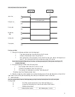
68
I C5 ½Å ÄÚ ÅÌ ¹Ü
1 0K 39 50 X2
1 ¦Ì FX 2
1 ¦Ì FX 2
1 0K 39 50 X2
+ 5V
1 0K
1 0K
1 0K
1 0K
I C4 m ou nt
10K
1
2
3
102
15
16
17
18
+5V
-5V
CPU
13
2. Disco pound the Principle Chart
2.1 CPU
:
:
:
:
(IC): is the core of the whole electric control board, comprised by many diodes, integrate elements and circuits,
such as A/D transformer, D/A transformer, clock, decoder and voltage comparisor, etc.
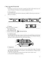
2.2 Power supply circuit:
Quality of the power supply will directly affect the performance & stabilization of the whole electric control section.
Below is the circuit diagram:
0
L
N
2 . 5 A - 3 . 5 A
1 0 K 5 6 1
0 . 0 3 3 ¦ Ì F
6 3 0 V
T
4 0 0 4 X 4
2 2 0 0 ¦ Ì F 3 5 V
1 0 4
7 8 1 2
2
3
1 0 0 ¦ Ì F 2 5 V
1 0 0 ¦ Ì F 2 5 V
1 0 4
7 8 0 5
3
+ 5 V
5 0 ¦ ¸
1 0 4
2.3 Sensors:
Sensors can be divided into three types:
1) Room temperature sensor
(Room temperature detecting)
2) Indoor coil temperature sensor
3) Outdoor coil temperature sensor
2.4 Indication lamp board.
There are four kinds of indication lamps on the board. They are economical, powerful, timing & operation indication
lamps. HS 0038 signal receiver receives signals, then send the signals to CPU for processing, decoding and
executing etc. And the indication lamps show clearly which function is going on.
.
2.5 Stepping motor
1) When the unit is switched on, the air-intake grid will turn to the standard position according to the operation
mode with a speed of 2500pps. When the unit is switched off , the air-intake grid will turn 149 degree toward the
closing direction with the same speed.
2) Ways of the air-intake grid swing can be divided into three states of natural, circulation, and stop.
3) The work principle of stepping motor is as follows
:
Anti-frosting & defrosting
Содержание TA-05CW
Страница 44: ...44 Part 2 Micro electric control system ...


